新聞中心

介面選型不只是規格比較 —
而是決定系統行為的關鍵,涵蓋架構、同步與實體層設計
在 Vision AI 系統設計中,討論焦點往往集中在模型精度、解析度與運算效能。然而,現場故障鮮少源自這些層面,而是來自影像資料在系統中的傳輸方式、同步機制,以及整體穩定性的維持。
隨著多攝影機架構在機器人、車載與工業檢測系統中逐漸成為標準配置,GMSL2 與 Ethernet 之間的選擇已不再只是介面層級的決策,而是會直接影響系統穩定性、同步精度與長期部署可靠性的架構選擇。
本文將解析兩種方案在系統架構上的本質差異、工程師常忽略的技術限制,以及介面選型如何在實際環境中影響系統行為。
系統架構差異:SerDes 鏈路 vs 網路化傳輸
從系統層面來看,GMSL2 與 Ethernet 代表兩種截然不同的資料傳輸模型。
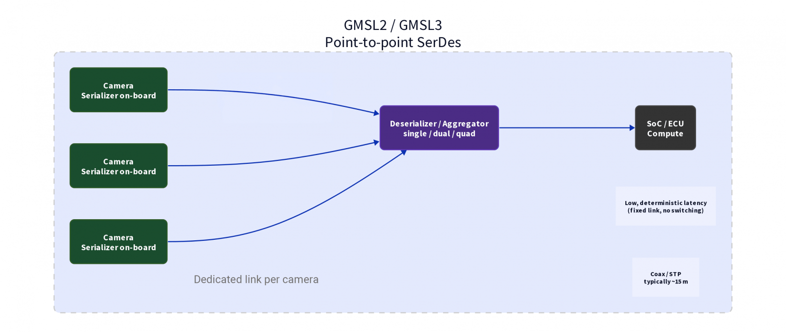
GMSL2 建立在 SerDes(串列器/解串列器)架構之上。影像資料在攝影機模組端完成序列化後,透過專用點對點鏈路傳輸。GMSL2 支援最高約 6 Gbps 的傳輸速率,GMSL3 則可達約 12 Gbps,通常透過同軸電纜或屏蔽雙絞線傳輸。有效傳輸距離最長約為 15 公尺,實際距離仍取決於 SerDes 世代、線材品質與系統設計。資料傳輸路徑固定,且不涉及封包交換與網路層處理,因此具備高度可預測的傳輸行為。
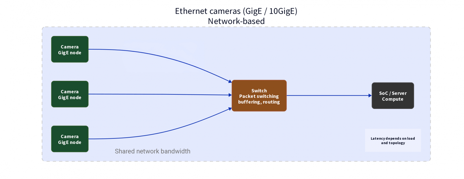
相較之下,Ethernet 將影像資料視為網路流量。攝影機作為網路節點存在,透過交換器進行封包傳輸後,再送至運算端。標準 GigE 支援 1 Gbps,10GigE 則可達 10 Gbps。在不使用中繼設備的情況下,單段線材傳輸距離通常可達約 100 公尺,並可透過網路設備進一步延伸。其資料路徑為動態且共享的網路傳輸架構。
這項根本差異,決定了系統的擴展方式,以及資料在負載條件下的行為表現。
延遲與確定性:固定資料路徑 vs 網路變異
GMSL2 與 Ethernet 在延遲行為上的差異,主要來自其傳輸架構。
GMSL2 提供相對具確定性的資料路徑。每台攝影機皆擁有專屬鏈路,延遲通常維持在微秒(µs)等級,且變動幅度低。這種特性使其特別適合需要穩定時序與即時反應的系統,例如 ADAS 環景攝影機陣列、自駕感測器融合,或工業 AMR 的即時視覺控制迴路。
Ethernet 則因封包化傳輸、交換器緩衝與網路負載影響,延遲具有變動性。實務上,延遲通常落在次毫秒至毫秒等級,取決於網路架構與優化程度。透過 QoS 與 TSN(Time-Sensitive Networking)等機制,可在一定程度上降低這類變異,但也需額外的系統層設計與配置。
實務上,在實驗室環境中表現穩定的系統,實際部署後仍可能出現難以預期的時序行為。
同步挑戰:硬體時序 vs 協定對齊
時間同步是多攝影機系統中常被低估的關鍵因素之一。
在 GMSL2 架構中,同步通常在硬體層實現 — 例如透過 GPIO tunneling 分發時序訊號,使多個感測器共享同一個時間基準。在適當的系統設計下,可達成微秒等級的同步精度,但實際表現仍取決於系統配置與硬體實作。
Ethernet 的同步方式則依系統設計而異。純網路架構通常仰賴 PTP(IEEE 1588 精確時間協定),其精度高度依賴網路設備、拓撲與各節點的硬體支援。在工業應用中,也常透過獨立的 M8 GPIO 接頭提供硬體觸發訊號,使多機同步不必完全依賴網路協定。相較於純軟體式同步,此方式具備更高的確定性。
當同步失準時,問題通常不會直接表現為系統失效,而是以較細微的異常形式出現 — 例如畫面錯位、追蹤不穩,或深度估測結果不一致。
頻寬 vs 資料流穩定性
頻寬是重要指標,但不足以單獨評估系統效能。
在 GMSL2 系統中,每條鏈路皆對應單一攝影機 — GMSL2 為每鏈路 6 Gbps,GMSL3 則為 12 Gbps — 裝置之間不會產生頻寬競爭。常見設計中,一顆解串列器可聚合最多四路攝影機串流。整體系統效能仍取決於後端 SoC 的處理能力。
在 Ethernet 系統中,頻寬為共享資源。即使總容量達到 10 GigE,多路資料流仍需競爭網路傳輸資源。在特定條件下,仍可能出現間歇性的延遲尖峰與短暫壅塞。
因此,頻寬充足並不代表資料傳輸穩定。
實體層考量:互連設計的角色
在高速影像系統中,實體互連設計會直接影響訊號品質與長期穩定性。
在 GMSL2 架構中,訊號路徑通常包含三個階段:攝影機模組端的板級 RF 介面、轉換至傳輸媒介的過渡層,以及連接至運算端的同軸或屏蔽雙絞線鏈路。
這些轉換點都涉及阻抗連續性、接觸穩定性與機械結構完整性。在多 Gbps 傳輸速率下,即使是細微的不連續或接觸變異,也可能隨時間累積並影響訊號完整性。
Ethernet 系統雖採用標準化線材與接頭,但其表現仍高度依賴線材品質、屏蔽設計與網路拓撲。
接頭選型:FAKRA、Mini-FAKRA 與工業 Ethernet 圓形接頭
在 Vision AI 系統的實體層設計中,RF 接頭與工業圓形接頭的選型,是影響訊號完整性與系統可靠性的關鍵因素。
.png)
GMSL2/GMSL3 系統:FAKRA 與 Mini-FAKRA
Mini-FAKRA 為 FAKRA 的小型化演進版本,在縮小體積的同時提供更高的連接密度。單一 Mini-FAKRA 外殼可整合最多四個同軸通道(Quad Mini-FAKRA),特別適合 ADAS 環景系統或駕駛監控系統(DMS)等空間受限的多攝影機應用。
GigE Vision 工業相機系統:M12 與 M8
在工業 Ethernet 攝影機系統中,主流配置採用雙接頭架構:M12 接頭負責 GigE 資料傳輸與 PoE 供電,M8 接頭則負責 GPIO 訊號,例如硬體觸發輸入與閃光燈輸出。
.png)
GMSL2 與 Ethernet 系統比較
| 比較維度 | GMSL2 / GMSL3 | Ethernet 攝影機 |
|---|---|---|
| 架構 | 點對點、具確定性 | 網路化、分散式 |
| 傳輸速率 | 約 6 Gbps(GMSL2)/ 約 12 Gbps(GMSL3) | 1 Gbps(GigE)/ 10 Gbps(10GigE) |
| 延遲 | 微秒等級、變動幅度低 | 次毫秒至毫秒等級,取決於網路架構 |
| 同步 | 硬體層 GPIO tunneling、微秒級精度 | PTP 協定或 M8 GPIO 硬體觸發 |
| 頻寬模型 | 各鏈路專屬、無裝置競爭 | 裝置間共享 |
| 線材與距離 | 同軸或 STP,最長約 15 公尺 | 雙絞線,約 100 公尺以上 |
| 供電方式 | PoC(Power over Coax) | PoE(Power over Ethernet) |
| 實體接頭 | FAKRA / Mini-FAKRA | M12(資料 / PoE)+ M8(GPIO) |
| 部署環境 | 車載、嵌入式、即時系統 | 分散式、長距離、工業網路 |
註:在量產條件下,GMSL 系統可透過單線整合(PoC)降低整體 BOM 與組裝複雜度;相較之下,Ethernet 則在既有網路基礎設施下具備較佳的擴展優勢。
工程師常忽略的常見誤解
- 誤解一:頻寬越高,效能就一定越好。即使頻寬足夠,延遲變異與同步誤差仍可能使系統效能下降。
- 誤解二:Ethernet 天生比較容易擴展。在需要微秒級同步的多攝影機即時系統中,擴展反而可能放大不穩定性。
- 誤解三:同步問題可以完全靠軟體解決。實際上,硬體支援仍是決定同步精度的關鍵。
- 誤解四:介面選型可以在設計後期再調整。實務上,若在設計後期更換介面,通常代表整條訊號路徑都需要重新驗證。
選型考量:讓介面符合系統需求
適合 GMSL2/GMSL3 的場景:
- 需要低延遲與高同步精度的 ADAS 環景或前視攝影機系統
- 工業 AMR 的即時視覺控制迴路
- 空間受限、需透過 PoC 實現單線整合的嵌入式平台
- 高 EMI 環境(如引擎室、焊接設備周邊等)
適合 Ethernet 工業相機的場景:
- 攝影機與運算端距離超過 15 公尺的大型工業視覺部署
- 需要整合既有網路基礎設施的系統
- 透過 PTP 或 M8 GPIO 觸發進行高速產線檢測的多機同步應用
常見問題
Q1:Ethernet 一定是可擴展系統的更佳選擇嗎?
Q2:為什麼頻寬看起來足夠,系統仍然會失敗?
Q3:GMSL2 適合多攝影機應用嗎?
Q4:FAKRA、Mini-FAKRA、M12 與 M8 接頭應該怎麼選?
Q5:同步問題可以完全靠軟體解決嗎?
Q6:實際部署中,系統不穩定最常見的原因是什麼?
結語:介面選型即架構決策
在現代 Vision AI 系統中,限制系統能力的瓶頸已不再只是模型本身,而是資料管線的穩定性。
GMSL2 與 Ethernet 代表兩種不同的系統設計思維。前者強調可預測性與控制性,後者則著重彈性與擴展性。
系統能否在實際部署中穩定運作,往往取決於這些取捨是否在設計初期即被正確評估。
核心建議
- 選擇 GMSL2/GMSL3:當你需要具確定性的低延遲、精準的硬體同步,以及高 EMI 或空間受限環境下的穩定運作。
- 選擇 Ethernet:當攝影機到運算端距離超過 15 公尺,或需整合至既有的大型網路基礎設施。
- 務必先定義:延遲容忍度、同步精度、傳輸距離與環境條件,再進行介面選型。
- 特別留意:實體層設計 — 接頭選型與阻抗匹配會直接影響現場長期可靠性。