新聞中心

LVDS is signal technology, not a connector
LVDS System Design Practical Trilogy | Part 1: Rethinking LVDSIn display, imaging, and high-speed data transmission, LVDS (Low-Voltage Differential Signaling) has always been an indispensable technology, particularly in automotive and industrial applications. However, LVDS is often directly referred to as a connector type, or even treated as a fixed interface specification.
This cognitive gap usually doesn't surface during spec reviews, but suddenly emerges during system integration: "Why is the signal still unstable with LVDS connectors?" "The spec says it supports LVDS, so why the interference?"
The Technical Nature of LVDS: Differential Signal Architecture
From an electrical perspective, LVDS employs differential signaling to transmit data. Signals are sent synchronously through a pair of conductors, with the receiver comparing only the voltage difference between the two lines, rather than a single signal's potential relative to ground. This design theoretically provides excellent noise rejection—and practical validation confirms this, provided the entire path is done right.
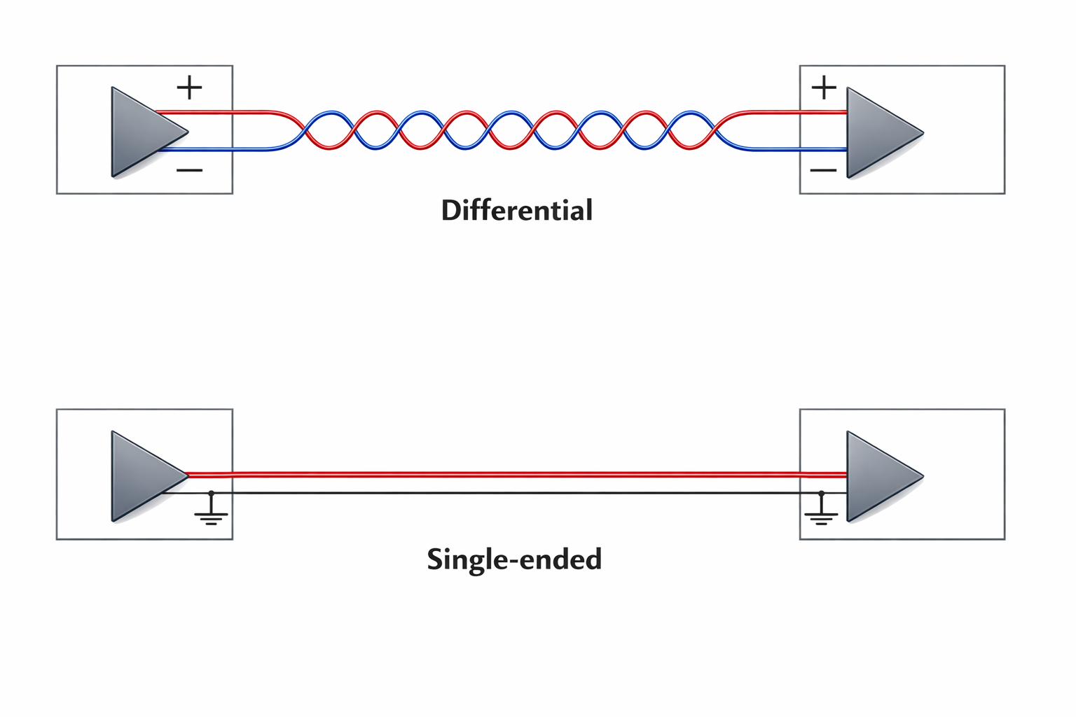
The core advantage lies in Common-Mode Noise Rejection. When both signal lines receive similar external interference, the receiver effectively filters out this common-mode noise and extracts only the differential signal. Combined with LVDS's low-voltage swing design, both power consumption and EMI performance surpass traditional single-ended signals. This is why LVDS maintains its edge in high-density PCBs and industrial equipment in strong electromagnetic environments.
LVDS's Position in Modern Systems
As system data rates continue rising, traditional single-ended or parallel transmission faces bottlenecks. Issues like skew, crosstalk, and noise often don't manifest during specification phase, but are exposed during system integration—usually at the customer site, not in the lab.
LVDS's differential architecture and controlled impedance design provide a solution balancing performance and reliability. It's widely applied in:
- Data interfaces between processors and display panels
- Transmission links between camera modules and image processing units
- Point-to-point high-speed imaging or control signal channels
- System internal interconnects with strict latency and synchronization requirements
In these applications, LVDS may not offer the highest bandwidth, but it's often the best balance between risk control and cost-effectiveness. When systems need to operate stably five or ten years later, this "not pursuing extremes but seeking stability" characteristic becomes an advantage.
System-Level Signal Integrity Considerations
In actual systems, LVDS performance depends on the entire signal path, not a single component. A complete LVDS transmission link typically includes: a differential driver, transmission medium (cable, PCB traces, connectors), and a differential receiver.
Many difficult-to-trace LVDS problems ultimately trace back to some detail in the signal path: impedance discontinuity, pair imbalance, or shielding broken at specific nodes. These problems share a common trait: not easy to detect during simulation, only appearing during system bring-up, and often intermittent—the most difficult type to handle.
We've encountered many cases: short cable testing shows everything normal, but after switching to production cables, sporadic errors appear; or it's stable in lab environment, but starts having noise interference at customer sites. The root cause almost always points to "the electrical characteristics of some link in the signal path don't match design expectations under real conditions."
Key Considerations for Interconnect Design
From an engineering practice perspective, evaluating whether an interconnect method suits LVDS depends not on which connector model is used, but on whether these electrical and mechanical conditions are met:
Differential Impedance Controllability
The entire signal path needs to maintain consistent differential impedance, typically 100Ω. This isn't "average 100Ω," but "100Ω throughout." Even a 0.5mm length difference can cause observable skew in high-speed signals.
Pair Geometric Symmetry
Ensure the differential pair's length and electrical characteristics match to avoid skew. Even minor mismatches introduce timing offsets that degrade signal quality.
Noise Isolation Capability
Provide appropriate shielding or isolation design to reduce external interference impact. In automotive environments, motors, ignition systems, and power converters are all potential interference sources.
Mechanical Reliability
Ensure contact interface stability doesn't degrade over long-term use. Vibration, thermal cycling, and insertion wear all affect contact impedance, which in turn affects signal quality.
As long as these conditions are met, various differential interconnect architectures have the capability to support LVDS electrically. This explains why many differential connectors in practice can be successfully applied to LVDS systems—provided designers understand and actually satisfy these conditions.
Hidden Risks in Cable Design
Based on practical experience, LVDS system problem points often aren't at connection ends, but in the cable itself. Inconsistent pair twist pitch, insufficient symmetry, or improper shielding design directly undermine differential signal advantages. When transmission distance increases, these effects become more significant.
A customer reported intermittent display flickering. The hardware team spent a week checking PCB, replacing ICs, adjusting software settings—the problem persisted. Finally discovered the supplier used pair cables with different twist pitch specifications in a particular batch, causing inconsistent differential impedance. After switching back to original spec cables, the problem immediately disappeared.
The Continuing Evolution of LVDS
Although high-speed serialization technologies (MIPI, USB Type-C, PCIe) continue developing, LVDS still holds an irreplaceable position in specific applications. In systems requiring low latency, deterministic timing, and high stability, LVDS remains a reliable technology choice.
Many modern systems adopt hybrid architectures, allowing LVDS and other high-speed interfaces to serve their respective roles, achieving optimal system performance configuration. For example, high-resolution images might use MIPI CSI, but synchronization control signals still use LVDS because the latter's latency is more predictable.
Conclusion: Return to Technical Fundamentals
LVDS is a signal transmission technology, not a connector specification or platform standard. Building a stable LVDS system requires deep understanding of electrical characteristics and systematic mastery of the entire signal path.
When design teams can think from the system level rather than focusing only on individual components, LVDS can deliver its proper technical value in practical applications. This technical value stems from respect for fundamental principles and attention to practical details.