新聞中心

1. What is a PCB Connector?
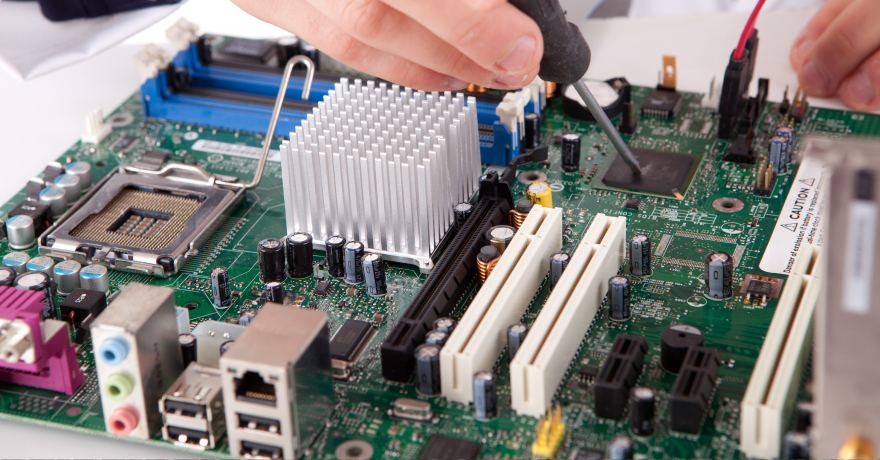
A PCB (printed circuit board) connector is a crucial component that facilitates the transfer of power or signals within circuits and electronic devices. It can be used to connect multiple PCBs or different components within a single PCB to create reliable and efficient conductive pathways, enabling the smooth operation of electronic systems.
A typical PCB connector consists of two main parts: the housing and the contacts. The housing refers to the outer shell that is often made of plastic or metal. It provides mechanical support and protection for the internal components. Depending on the specific circuit board connector type and application, the contacts may come in various forms, such as pins, sockets, or edge connectors. They are the conductive elements of PCB connectors, usually made of copper or other conductive materials, that establish the electrical connection between the PCB components or boards.
Moreover, it is also important to note that PCB board connector types can be further categorized by how they are connected and what they are used for. Thus, we will further discuss these PCB board connector types in the following sections to give you an overview of their features and common applications. By understanding their differences, you can choose the most suitable one for your unique project to create versatile electronic devices, promoting simple assembly, efficient maintenance, and easier upgrades for long-term performance.
2. PCB Connector Types: By Connection Method
Based on how they link components or boards within an electronic device, PCB connectors can be classified as board-to-wire, wire-to-board, or board-to-board connectors.
2.1. Board-to-Wire Connectors
Board-to-wire (board-to-cable) connectors establish connections between a PCB and external components, such as sensors or switches, with wires. Examples of this PCB connector type include crimp connectors, where a metal contact is crimped onto the wire and inserted into a housing, as well as insulation displacement connectors (IDC), which create connections without needing wire insulation removal.
2.2. Wire-to-Wire Connectors
During the prototyping stages, two PCBs may be linked directly through wires with wire-to-wire connectors (cable-to-cable connectors), where one end of the connection is permanent, while the other is detachable. This enables modular configurations and simpler wiring which offer greater flexibility for easy part replacement in prototype devices.
2.3. Board-to-Board Connectors
Board-to-board connectors link two or more PCBs together without wires. They allow boards to be stacked or arranged in compact layouts, either parallelly (using mezzanine board-to-board connectors) or perpendicularly (with orthogonal board-to-board connectors), depending on design needs.
By eliminating the need for wires, board-to-board connectors can provide more space efficiency than other circuit board connector types, making them valuable for various high-density applications, including computer systems, telecommunications equipment, automotive electronics, industrial automation, and more. Moreover, the design of board-to-board connectors enables effortless assembly and disassembly, saving labor time and costs.
3. PCB Connector Types: By Function
In this section, we will explore some of the most common types of PCB connectors categorized by their functions, as some are specifically made for power delivery, data transfer, memory storage, or signal transmission.
3.1. Power Connectors
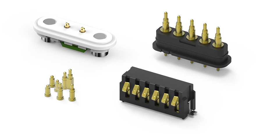
Power connectors are essential interfaces that connect a power source to electronic devices, delivering electricity safely and efficiently to a PCB. They typically consist of plug-and-socket configurations that accommodate specific voltage and current requirements. They are also designed to withstand the heat and stress generated during operation.
Moreover, power connectors are available in various forms, including barrel connectors, blade connectors, and screw terminals, which cater to different power needs and design constraints of each device, whether it's for consumer electronics or industrial equipment.
3.2. Card Edge Connectors
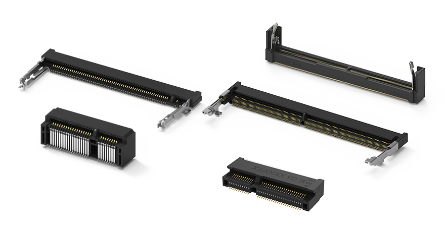
Card edge connectors are specifically for interfacing with the edge of a circuit board. They are characterized by rows of contacts that mate with corresponding connectors on the PCB. Their design is highly versatile with options for single-row, double-row, or multiple-row contacts, allowing them to adapt to the needs of various electronic devices and systems.
The design of card edge connectors also allows for quick, secure connections with high signal integrity, making them ideal for applications where rapid assembly or replacement is needed, such as in PCI slots in computers. They are also widely used in gaming consoles and telecommunications equipment due to their durability and efficient data transmission capabilities.
Common types of card edge connectors include Mini PCIe Connectors for connecting compact networking cards and MXM Connectors which connect graphics processing units (GPUs). Other notable examples include the SO-DIMM Connectors, primarily used for mounting RAM modules, and M.2 connectors which support high-speed data transfer for solid-state drives (SSDs) and WiFi modules.
Among these interfaces, M.2 connectors have become increasingly popular due to their transmission capabilities and compact form factors. For a deeper dive into different types of M.2 components, check out our article below:
➤ What are the Different M.2 Types: Protocols, Keys, & Slots
3.3. Audio/Video Connectors
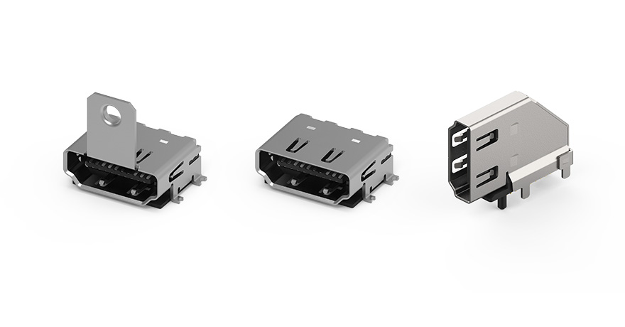
This type of input/output (I/O) connector is specially designed to transmit audio and video signals between various devices. These connectors vary widely in design and are used for both analog and digital connections. Examples include:
-
HDMI Connectors: A high-speed digital interface that transmits both audio and video signals over a single cable, frequently used for high definition (HD) visuals and 7.1 surround sound systems.
-
DP Connectors: An interface that supports high-resolution digital signals for video and audio with higher refresh rates and larger data throughput. DP also supports daisy chaining, allowing for multi-display in workstations or other applications.
-
VGA Connectors: An analog video interface commonly used to connect computers to monitors or projectors.
-
RCA Connectors: A type of connector used for stereo audio and analog video signals, especially for older televisions.
-
3.5mm Audio Jack: A common connector for headphones, microphones, and other audio devices.
3.4. Modular/Ethernet Connectors
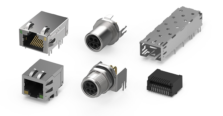
Modular/Ethernet connectors offer reliable and efficient data transmission between network devices. The most common example within this category is the RJ-45 connector which is typically used for Ethernet connections in local area networks (LANs). Other prevalent interface types include RJ-11 for telephone lines, BNC for coaxial cable applications, and fiber optic connectors for internet networks.
In addition to enabling high-speed data transfer, modular/Ethernet connectors also boast a modular design that allows users to connect and disconnect cables easily within home networks, office networks, or data centers.
3.5. Memory Connectors
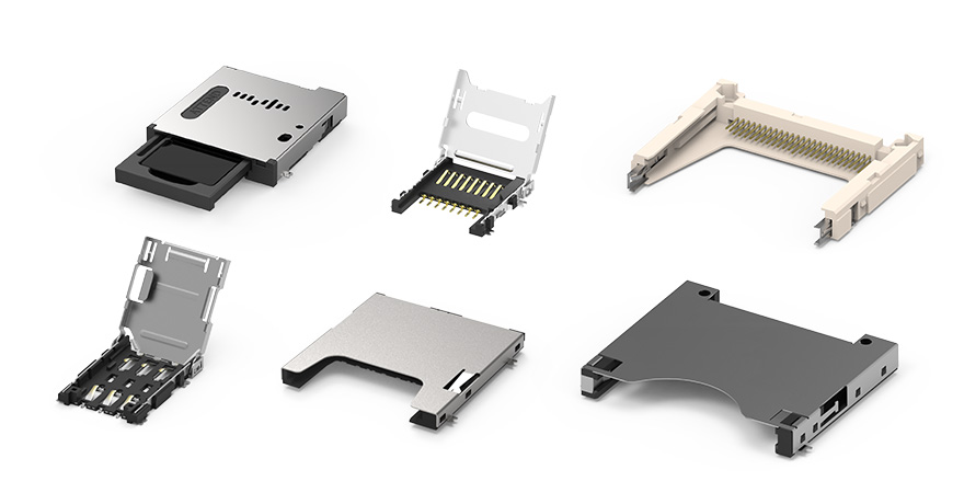
Memory connectors are interfaces used to connect memory cards or modules, enabling data storage and retrieval within a device. They come in various formats like SD, microSD, CompactFlash, SIM, and more.
The applications of memory connectors span from consumer electronics, such as smartphones and cameras, to industrial systems like IIoT devices and automotive systems. To find the optimal type of connector, users will have to consider factors such as the required data transfer speed, storage capacity, the form factor of the device, and the environmental conditions within the operating space. So, make sure to consult an expert supplier if you are unsure of your choice.
4. PCB Connector Types: By Specialized Design
The PCB connector types discussed in this section are designed to handle the varying data transfer rates, power capacities, environmental conditions, system architectures, and other operational requirements of different applications.
4.1. USB Connectors
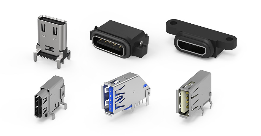
USB connectors are input/output (I/O) connectors that provide a versatile interface for data transfer and power delivery in modern consumer devices, from smartphones and laptops to peripherals like keyboards and printers. They also come in different formats and the most common ones include:
-
USB-A: The classic, rectangular type found on computers and laptops, often connecting devices like mice and flash drives.
-
USB-B: A larger connector that is typically used for devices like printers and older electronics.
-
Micro-USB: Commonly used in small devices, such as smartphones and cameras, but it’s increasingly being replaced by USB-C.
-
USB-C: A versatile type of USB connector that is currently the most widespread for modern electronics. It provides faster data transfer, higher power delivery, and the convenience of reversible connection.
4.2. Automotive Electronics Connectors
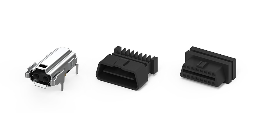
Built to withstand the harsh conditions of the automotive environment, this type of PCB connector is engineered to resist vibration, temperature fluctuations, and moisture. They must also adhere to the rigorous USCAR-20 standards set by SAE International, ensuring safe and reliable performance over the vehicle's service life.
These connectors can be used to achieve various functions in the vehicle, including engine control, transmission control, airbag systems, infotainment systems, and lighting systems. There are also Onboard Diagnostics 2 (OBD2) connectors that allow mechanics and diagnostic tools to access the vehicle’s self-diagnostic system, enabling the retrieval of Diagnostic Trouble Codes (DTCs) and real-time data for efficient maintenance or repairs.
Additionally, single-pair Ethernet (SPE) connectors have been gaining popularity in automotive applications as well. It allows for data and power transmission over a single pair of wires. This makes them ideal for enclosures within vehicles, including in-vehicle sensor networks and control systems, where space efficiency and lightweight properties are crucial. While SPE connectors aren’t waterproof or dustproof, they still provide basic contact resistance, so they can be used for the interior of vehicles or any other environments that require protection ratings less than IP65.
4.3. FFC/FPC Connectors
.jpg)
FFC (Flexible Flat Cable) and FPC (Flexible Printed Circuit) connectors are low-profile connectors that support flexible, high-density connections between circuits. These connectors are widely used in compact devices with space constraints, such as mobile phones, laptops, and wearables.
In terms of design, FFC connectors consist of flat, ribbon-like cables, while FPC connectors are thin, flexible circuit boards. Both types feature varying pitch sizes, typically between 0.3 mm to 2.54 mm, and can have anywhere from 4 to 50 pins, allowing them to adapt to diverse applications where versatility and space efficiency are critical.
4.4. Circular Connectors
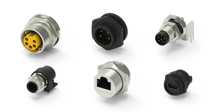
Circular connectors, also known as aviation plugs, are used for critical applications where durability and reliability are crucial, such as aerospace, military, and industrial environments. They are designed with a cylindrical, rugged structure that can handle high currents and resist electromagnetic interference (EMI), and they often include waterproof and dustproof features for increased resistance.
On top of that, circular connectors are available in various sizes and configurations, with different numbers of pins and varying levels of sealing, offering versatility for transmitting power, signals, or data, while ensuring efficient performance in harsh and demanding conditions.
5. Types of PCB Connector Mounting
PCB connectors can be mounted on a circuit board using either through-hole mounting or surface mount technology (SMT). Selecting between through-hole and SMT depends on factors such as durability needs, board space, and production costs, with each method offering distinct advantages for different types of electronic applications.
5.1. Through-Hole Mounting
In through-hole mounting, the connector leads are inserted into pre-drilled holes in the PCB and soldered to pads on the opposite side. This method creates a strong mechanical bond, making it ideal for connectors that endure physical stress, such as those used in industrial or automotive settings.
Through-hole mounting is reliable for components that need added stability, but the process requires drilling, which can increase production costs and reduce the available surface area for other circuitry. While this method is often slower and more labor-intensive than SMT, it remains useful for heavy-duty applications that involve harsh conditions and frequent exposure to vibration.
5.2. Surface Mount Technology (SMT)
Surface mount technology (SMT) involves soldering the connector directly to the surface of the PCB without drilling holes. This allows for smaller connectors and denser component layouts, which is beneficial for compact devices like smartphones and laptops. Additionally, SMT is compatible with automated assembly, such as wave soldering and pick-and-place machinery, streamlining production and potentially lowering manufacturing costs.
However, SMT connectors may lack the mechanical durability of through-hole connectors, especially in high-stress environments. Hence, SMT requires careful design considerations to ensure reliable connections, as misalignment or improper soldering can affect performance.
6. How to Select a PCB Connector?
When selecting a PCB connector, consider the following key factors to ensure that the choice meets the device’s functional, environmental, and compliance needs:
6.1. Electrical Specifications
To ensure optimal current and voltage ratings, it’s essential to select connectors with ratings that meet or exceed the device’s power requirements so that the connector can operate safely without overheating or failing. Also, consider choosing a PCB connector with low contact resistance to ensure efficient signal transmission and minimize power loss.
Once you have determined the best option, it is still important to practice derating by operating connectors below their maximum capacities to reduce thermal stress and electrical load, as it will help improve the PCB connector’s longevity and reliability.
6.2. Connection Reliability
For a reliable connection and signal integrity, the PCB connectors should have high-quality contacts with impedance, crosstalk, and other properties compatible with your current infrastructure to minimize the risk of signal degradation and power loss.
6.3. Mating Cycles
Mating cycles represent the number of times a PCB connector can be repeatedly plugged and unplugged without performance loss. This information is often pre-rated by manufacturers through various tests and provided in the connector’s datasheet. If your application requires frequent disconnecting and reconnecting, a connector with higher mating cycle ratings may be better suited.
6.4. PCB Layout and Design
The connector’s size must fit within the board layout and device enclosure. Its shape should also be chosen based on how easily it can be connected and disconnected from the board or other components.
Furthermore, the PCB connector’s pin configuration or pin layout will determine how the signals are transmitted, so make sure to consider its compatibility with your application as you make your choice to ensure effective connections.
6.5. Environmental Resistance
Durability and resistance are essential for connectors exposed to extreme environmental conditions like fluctuating temperatures, humidity, or corrosive chemicals. As such, consider choosing materials like corrosion-resistant metals and heat-stable polymers to ensure reliable performance under these stresses.
In addition, connectors may also face mechanical stresses like vibrations in industrial and automotive settings, so it may be necessary to incorporate a locking mechanism into the PCB connector to prevent accidental disconnections and maintain smooth operation.
6.6. Industry Compliance and Certifications
Compliance with industry standards is essential when selecting PCB connectors, as these standards ensure safety and environmental responsibility. For example, standards such as the ISO (International Organization for Standardization) cover quality management, safety, efficiency, and compatibility, while the RoHS (Restriction of Hazardous Substances) limit the use of hazardous materials like lead and mercury in electronic components. By purchasing PCB connectors from manufacturers that adhere to these standards, the reliability and performance of the product is better guaranteed.
7. Reliable PCB Connector Solutions at ATTEND Technology
As you learn how to differentiate each PCB connector type and its functions, you can effectively choose between them to ensure the reliability and performance of your devices.
As a leading PCB connector supplier, ATTEND offers an extensive range of high-quality connectivity solutions, including memory connectors, power connectors, card edge connectors, and so much more, catering to diverse sectors such as industrial, networking, transportation, and consumer electronics.
What sets ATTEND apart is our unwavering commitment to quality. Our connectors are created from superior materials that can withstand operational temperatures of -40°C to +85°C, ensuring durability and long-lasting performance, even in challenging environments. With high mating cycles and strict quality control measures, we guarantee that every connector meets the highest industry standards under our ISO9001 certification and compliance with RoHS regulations.
We also pride ourselves on providing exceptional customer service. Our dedicated sales and technical teams are available globally to assist you in finding the right solutions tailored to your specific needs.
Explore our connector solutions today
and elevate your projects with ATTEND!