
Ethernet already runs the control level of most industrial networks. The harder problem is the last stretch to the field: sensors, actuators, and instruments, where multi-pair cable adds size, weight, and installation effort that a 10 Mb/s device link does not need.
Single Pair Ethernet (SPE) closes that gap by running Ethernet over one balanced pair. Depending on the PHY, an SPE link can span a few meters inside a machine or up to 1,000 m across a plant, and it can deliver power either on the same pair or alongside it.
SPE is also not a single standard. An SPE link is built from four separately specified layers: transmission, power, connector interface, and cabling. The way these layers combine explains why products sold as “SPE” can look nothing alike.Key Takeaways
- SPE is Ethernet over one balanced pair, defined primarily by the IEEE 802.3 BASE-T1 family.
- The PHY and the connector are separate decisions. IEEE defines transmission; IEC 63171 defines the physical connector interface.
- SPE connectors are not automatically interchangeable, even when they share a familiar format such as M8.
- PoDL / SPoE and Hybrid SPE use different power architectures.
- The current IEC 63171-7 Ed.2 draft points toward broader interface harmonization, while existing IEC 63171-2, -5, and -6 implementations remain valid and in use.
Where SPE Fits in the Industrial Network
In a typical architecture, SPE extends Ethernet from the control level to field devices:
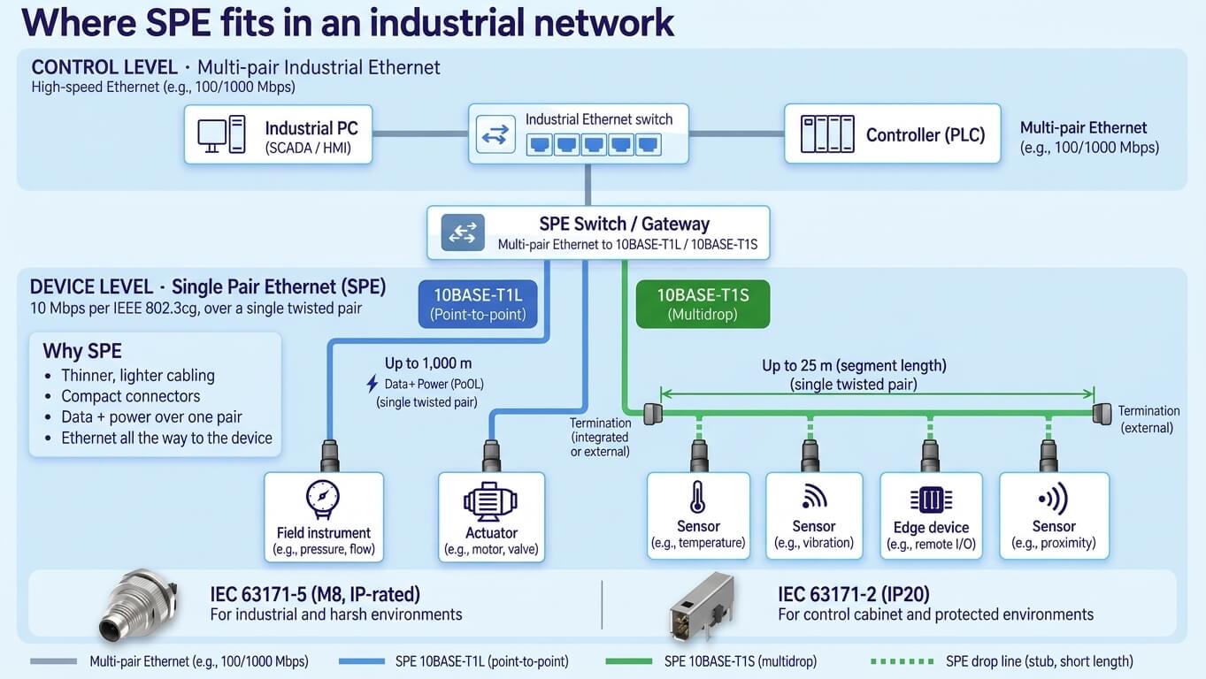
Multi-pair Ethernet stays where bandwidth matters most: switches, controllers, and industrial PCs. SPE handles device-level links, where cable diameter, connector size, reach, and power delivery carry more weight than peak data rate.
Two IEEE 802.3cg variants cover this layer. 10BASE-T1L runs point-to-point links up to 1,000 m and suits field instruments and actuators spread across a plant. 10BASE-T1S connects multiple nodes on a shared segment up to 25 m, a better fit for dense sensor clusters inside a machine. With Power over Data Line (PoDL), a single T1L link can carry both data and power to the device.
Typical application areas include process automation, machine-level communication, building automation, distributed sensing, robotics, and edge-connected industrial equipment.
The SPE Standards Stack
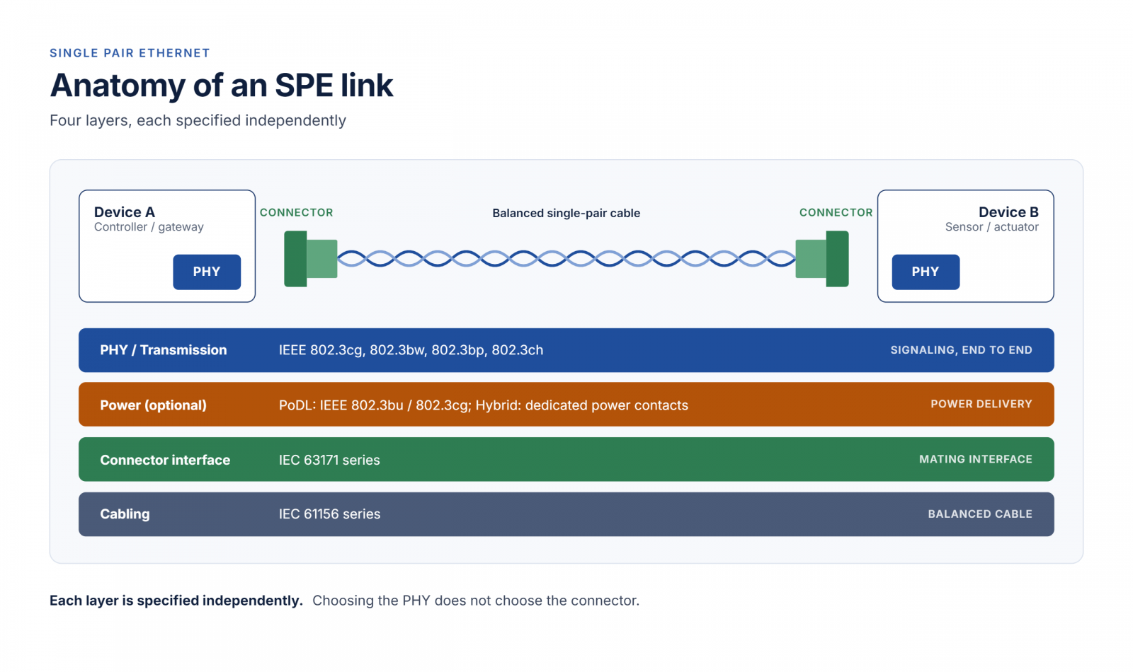
| Layer | What It Defines | Key Standards |
|---|---|---|
| PHY / Transmission | Data rate, reach, signaling, topology | IEEE 802.3cg, 802.3bw, 802.3bp, 802.3ch |
| Power | Power delivery over the SPE link | IEEE 802.3bu PoDL; additional power provisions in 802.3cg |
| Connector Interface | Mating interface, contacts, locking, environmental characteristics | IEC 63171 series |
| Cabling | Balanced single-pair cable construction and channel performance | IEC 61156 series and related structured cabling standards |
Each layer is specified independently. The same 10BASE-T1L PHY can terminate in a compact cabinet connector or in an industrial circular interface. Choosing the PHY does not choose the connector.
BASE-T1: Matching Data Rate to Reach
BASE-T1 is the family of Ethernet physical-layer technologies designed to run over one balanced pair.
| PHY | IEEE Amendment | Data Rate | Typical Reach | Topology | Applications |
|---|---|---|---|---|---|
| 10BASE-T1L | IEEE 802.3cg | 10 Mb/s | Up to 1,000 m | Point-to-point | Process instrumentation, building automation, distributed field devices |
| 10BASE-T1S | IEEE 802.3cg | 10 Mb/s | 15 m point-to-point; up to 25 m multidrop | Point-to-point / multidrop | Sensors, controllers, embedded device networks |
| 100BASE-T1 | IEEE 802.3bw | 100 Mb/s | 15 m | Point-to-point | Automotive electronics, embedded systems |
| 1000BASE-T1 | IEEE 802.3bp | 1 Gb/s | 15 m Type A / 40 m Type B | Point-to-point | Automotive backbones, industrial equipment |
| 2.5/5/10GBASE-T1 | IEEE 802.3ch | 2.5 / 5 / 10 Gb/s | 15 m | Point-to-point | High-bandwidth sensing, imaging, automotive networks |
10BASE-T1L is the PHY behind most of the industrial interest in SPE. With a reach of up to 1,000 m, it runs Ethernet directly to field devices that would otherwise need additional network infrastructure. It is also the physical layer of Ethernet-APL, the process-automation variant that supports hazardous areas through 2-WISE (2-Wire Intrinsically Safe Ethernet), defined in IEC TS 60079-47.
10BASE-T1S covers the opposite case: short-reach networks, including multidrop segments in which several nodes share one pair. It fits embedded device networks, in-machine communication, and distributed sensors.
100BASE-T1, 1000BASE-T1, and Multi-Gig BASE-T1 apply the same single-pair principle to higher-bandwidth applications such as automotive networks and imaging.
Power: PoDL / SPoE vs. Hybrid SPE
Many field devices need power as well as data. SPE offers two ways to deliver it.
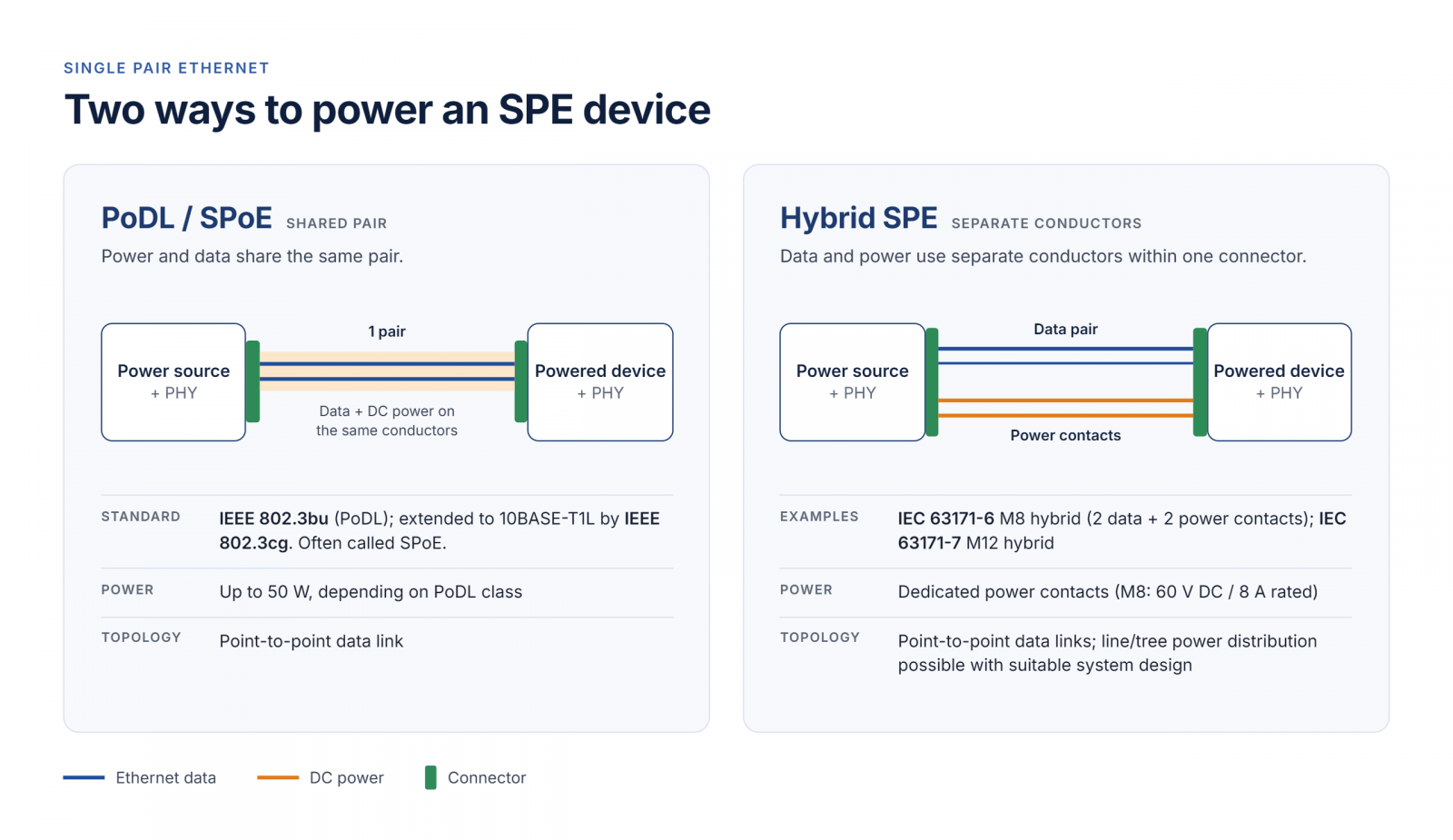
| Approach | Data Path | Power Path | Basic Architecture |
|---|---|---|---|
| PoDL / SPoE | SPE pair | Same SPE pair | Power and data share one pair |
| Hybrid SPE | SPE pair | Dedicated power contacts | Data and power share one connector, not one pair |
PoDL (Power over Data Line), introduced in IEEE 802.3bu, sends power over the same pair that carries Ethernet data. IEEE 802.3cg later extended power provisions for 10 Mb/s single-pair links, commonly referred to as SPoE (Single-pair Power over Ethernet). The appeal is simple: one pair does everything.
Hybrid SPE keeps data on the SPE pair and adds dedicated power contacts in the same connector. Data and power share one connection but travel on separate conductors, which suits devices whose power needs exceed what the data pair can practically carry.
IEC 63171: One Series, Several Mating Faces
BASE-T1 defines how Ethernet travels over the pair, but it does not define the connector. That is the role of the IEC 63171 series, which contains several distinct physical interfaces.
| IEC Standard | Interface Format | Key Characteristics | Application Context |
|---|---|---|---|
| IEC 63171-2 | Compact 2-way SPE | IP20-oriented compact interface | Controllers, gateways, protected equipment |
| IEC 63171-5 | Circular 2-way SPE | M8 / M12 locking interface; IP65 / IP67 | Sensors, actuators, field devices |
| IEC 63171-6 | Industrial SPE interface family | IP20 and M8 / M12 circular formats; IP65 / IP67; data and selected data/power configurations | Industrial cabinet and field connectivity |
| IEC 63171-7 Ed.1 | Size 12 circular, 4–7 ways | M12 / P12 / C12; data + power; multiple coded mating interfaces | Industrial data/power connectivity |
IEC 63171-2, -5, and -6
These three parts grew out of two industry camps:
SPE System Alliance: historically backed IEC 63171-2, a compact IP20 interface, and IEC 63171-5, a circular interface for industrial environments.
SPE Industrial Partner Network: promoted IEC 63171-6, widely known by the industry term T1 Industrial.
IEC 63171-6 is often read as a hybrid standard. In fact, it covers SPE data interfaces as well as configurations with additional power contacts.
This history has a practical consequence: “M8 SPE” is not a complete specification. An IEC 63171-5 M8 connector and an IEC 63171-6 M8 connector share a size, not a mating face. Specifications should name the applicable IEC 63171 part.
IEC 63171-7 and the Move Toward Harmonization
IEC 63171-7 Ed.1, published in 2023, defines shielded size 12 circular connectors with 4 to 7 ways for data and power. Three locking styles are available:
- M12 screw locking
- P12 push-pull locking
- C12, which combines both
Coded mating interfaces prevent incompatible configurations from mating. In every coding, two contacts plus the shield carry differential data up to 600 MHz, and the remaining contacts provide dedicated power paths. PoDL can also be superimposed on the data pair through compatible IEEE 802.3bu implementations.
IEC 63171-7 is also the standard that both former camps now back. The SPE System Alliance and the SPE Industrial Partner Network began coordinating in 2025 and combined under the Single Pair Ethernet Association in 2026. Together, they support IEC 63171-7 and the development of a uniform IP20 SPE mating profile.
The current Ed.2 draft (prEN IEC 63171-7:2026) points toward broader interface harmonization, adding IP20 rectangular, M8 and M12 2-way data interfaces, and extending M12 data/power configurations to up to 7 ways.
Existing designs are unaffected. IEC 63171-2, -5, and -6 remain valid, and the direction of development is greater interoperability rather than immediate replacement.
Cabling Completes the Channel
A connector is only one part of the physical channel. SPE also needs balanced single-pair cable whose electrical characteristics match the PHY, the link length, and the operating environment. The IEC 61156 series covers balanced digital communication cables, including single-pair constructions.
Key selection factors include:
- transmission distance
- conductor size
- shielding
- EMC environment
- fixed versus flexing installation
- required data rate
Connector, cable, and PHY work as one channel and are best engineered together.
What Defines an SPE Implementation?
The connector is only one of five decisions that define an SPE link:
| Layer | Design Question | Options |
|---|---|---|
| PHY / Reach | How far, and how fast? | 10BASE-T1L, 10BASE-T1S, 100BASE-T1, 1000BASE-T1, Multi-Gig BASE-T1 |
| Connector Interface | Which mating face? | The applicable IEC 63171 part |
| Environment | Where is it installed? | Protected cabinet, machine, or field; vibration; ingress protection |
| Power | How is the device powered? | Data only, PoDL / SPoE, or Hybrid power contacts |
| Cabling | What must the cable handle? | Transmission performance, shielding, conductor size, mechanical requirements |
Two systems can both qualify as SPE and still differ on every row.
ATTEND Industrial SPE Connectivity
ATTEND’s SPE range spans three IEC 63171 parts. It covers compact PCB connections for protected equipment, M8 circular connectivity for field devices, and hybrid data/power connections.
| ATTEND Solution | IEC Interface | Implementation | Example Equipment |
|---|---|---|---|
| SPE IP20 Jack | IEC 63171-2 | 2-pin IP20 SPE jack with right-angle DIP PCB mounting | Industrial controllers, gateways, and control cabinet equipment |
| M8 SPE Two Piece | IEC 63171-5 | 2-pin M8 SPE connector with a two-piece design; available in a straight SMD configuration | Industrial sensors, actuators, and industrial equipment |
| M8 Hybrid SPE | IEC 63171-6 | 4-pin M8 Hybrid SPE with 2 data contacts and 2 dedicated power contacts; available in straight and right-angle PCB jack configurations | Industrial automation, sensors, and equipment requiring data transmission and dedicated power connections |
| SPE Cable Assemblies | IEC 63171-2 / -5 / -6 | IP20, M8 SPE, and M8 Hybrid SPE cable assemblies for data transmission or combined data and dedicated power connections, depending on the interface | Field wiring between industrial equipment, sensors, and control systems |
Each connector or cable assembly uses a specific IEC 63171 mating interface, depending on the product configuration.
The portfolio itself shows why this matters. The M8 SPE Connector (IEC 63171-5) and the M8 Hybrid SPE Jack (IEC 63171-6) share a format but belong to different mating-interface families, so they are not intermateable. Mating compatibility is confirmed by matching the IEC 63171 part at both ends of the link, not by connector size.
Frequently Asked Questions
No. SPE is an Ethernet physical layer based on one balanced pair. Industrial Ethernet is the broader architecture: protocols, switches, controllers, network devices, cabling, and physical interfaces. SPE can form one part of an Industrial Ethernet system.
Both are 10 Mb/s PHYs defined in IEEE 802.3cg. 10BASE-T1L is a long-reach point-to-point PHY, with links of up to 1,000 m. 10BASE-T1S targets short-reach networks, with 15 m point-to-point links and multidrop segments of up to 25 m.
T1 Industrial is the industry term commonly used for the SPE mating interface standardized in IEC 63171-6. It is not a separate standard, so specifications should reference IEC 63171-6 directly.
No. They belong to different mating-interface families, even though both use an M8 format. Equipment documentation and purchase specifications should name the applicable IEC 63171 part rather than relying on “M8 SPE.”
IEC 63171-7 defines size 12 circular SPE connectors with 4 to 7 ways for data and power, using M12, P12, or C12 locking styles. Ed.1 was published in 2023. The Ed.2 draft (prEN IEC 63171-7:2026) proposes adding 2-way data interfaces in IP20, M8, and M12 formats.
No. Multi-pair Ethernet remains the right choice for network infrastructure and high-bandwidth equipment. SPE extends Ethernet to devices and environments where smaller interfaces, reduced cabling, longer reach, or device-level connectivity bring practical advantages.
From SPE Standards to Industrial Connectivity
The formation of the Single Pair Ethernet Association and ongoing standardization around IEC 63171-7 indicate a move toward greater interface harmonization, while established SPE interfaces continue to serve existing applications.
For connector and cable suppliers, the practical role is not to define the Ethernet network itself, but to provide reliable physical connectivity that matches the relevant SPE transmission, interface, power, cabling, and environmental requirements.