
A single automation machine can carry dozens—sometimes hundreds—of M12 connection points linking sensors, actuators, vision systems, I/O modules, and control equipment. When every one of those connections requires manual threading, tightening, and verification, the locking mechanism affects far more than the connector itself. It shapes assembly time, mechanical layout, service access, and installation consistency in the field.
M12 Push-Pull connectors replace traditional threaded coupling with a push-in locking mechanism that simplifies the mating process. Faster installation, however, does not make Push-Pull the right choice for every system. Selection should still come back to how the equipment is actually assembled, the operating environment, maintenance frequency, and compatibility with the existing M12 architecture.
M12 Push-Pull is well suited to applications where installation speed, limited space, high port density, or frequent servicing are important. Threaded M12 remains a practical choice for established systems, fixed installations, and applications that prioritize compatibility with existing M12 architectures. The better choice depends on the equipment layout, maintenance strategy, and actual interface requirements.
New to M12 connectors? See our M12 Connector Guide: Pinouts, Codes & Industrial Uses for an overview of connector codes, pin layouts, standards, and common industrial applications.
Why the M12 Locking Mechanism Matters
The electrical interface is only one part of an industrial connection system. The mechanical locking method also determines how technicians handle the connector, how much clearance each port requires, and whether connection quality stays consistent across production and field installation.
The locking mechanism deserves particular attention when:
- Multiple M12 ports are arranged in close proximity
- Connectors sit inside tight enclosures or recessed pockets
- Operators must install connectors while wearing gloves
- Equipment modules require regular service or replacement
- Large numbers of connections must be made repeatedly
- Connection quality depends on correct coupling torque
In these situations, a connector can meet every electrical requirement and still become a bottleneck in assembly or maintenance.
How M12 Locking Mechanisms Work
Threaded M12 and M12 Push-Pull use the same familiar M12 form factor, but the way the connection is mechanically secured is different. That difference changes how the connector is installed, how much access space is required, and how quickly technicians can connect or disconnect equipment.
.png)
Rotate and tighten the coupling nut
A traditional threaded M12 connector secures the cable-end connector to a compatible device-side receptacle by rotating the coupling nut. The design is widely used across sensors, actuators, industrial Ethernet, field devices, and power connections.
- Access to the coupling nut
- Rotational clearance around the port
- Several turns to complete mating
- Torque control where specified
Practical implication: The connection itself is proven and reliable, but installation becomes more difficult when ports are densely arranged or positioned close to enclosures, cable ducts, or neighboring components.
Push straight in until the mechanism locks
An M12 Push-Pull connector is pressed directly into a compatible device-side receptacle until the locking mechanism engages. No rotation of a coupling nut is required; unmating is completed by releasing or pulling back the locking sleeve, depending on the product design.
- Shorter mating and unmating time
- Typically tool-free mating
- No coupling-nut rotation
- Less rotational clearance required
Different M12 Push-Pull products may use different locking structures, interface standards, and compatibility designs. Actual mating compatibility should therefore be verified at the product level.
Practical implication: Push-Pull is not a wholesale replacement for threaded M12. Its main value appears when installation speed, confined space, or maintenance efficiency becomes a system-level constraint.
ATTEND M12 Push-Pull Interface Design
ATTEND M12 Push-Pull products follow IEC 61076-2-010 and use inner-locking or outer-locking structures depending on the connector configuration.
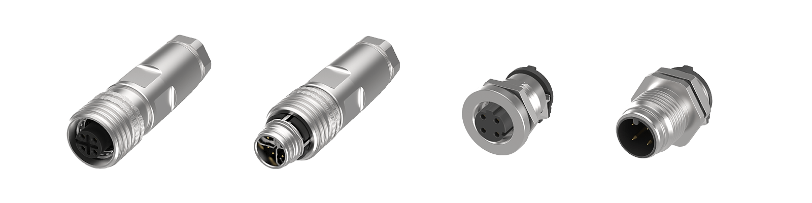
- Cable-side male: inner locking
- Cable-side female: outer locking
- Board-side female: inner locking
- Board-side male: outer locking
Compatible ATTEND board-side interfaces can mate with both IEC 61076-2-010 Push-Pull cable-side connectors and IEC 61076-2-101 conventional threaded M12 cable-side connectors.
Standards note: IEC 61076-2-012 is a separate M12 Push-Pull interface specification and should not be described simply as the “outer-locking version” of IEC 61076-2-010. The compatibility described above is specific to ATTEND product design and should not be assumed for all M12 Push-Pull products.
M12 Push-Pull vs. Threaded M12: Comparison
| Selection Criteria | M12 Push-Pull | Threaded M12 |
|---|---|---|
| Locking method | Push-in locking | Rotating threaded coupling |
| Installation | Push directly into a compatible port | Thread and tighten the coupling nut |
| Tool requirements | Typically tool-free mating | Torque tool may be required per installation spec |
| Clearance around ports | No significant rotational clearance needed | Space required to rotate the coupling nut |
| Installation speed | Suited to high-volume, repetitive assembly | More time per connection point |
| Serviceability | Suited to modules with regular service or replacement | Suited to long-term fixed connections |
| Port density | Suited to compact, closely spaced layouts | Requires clearance for coupling nut access |
| Locking consistency | Independent of manual tightening torque | Torque must be controlled per specification |
| Legacy compatibility | Mating interface must be verified | Widely deployed across installed equipment |
| Primary design driver | Assembly efficiency and serviceability | Proven compatibility and fixed installation |
The comparison makes one thing clear: this is not a choice between "fast" and "reliable." With correct selection, mating, and installation, both locking methods support dependable industrial connections. The real difference is how well each fits the equipment's assembly workflow and usage pattern.
How the Locking Method Affects Installation Workflow
Installation Time at High Connection Counts
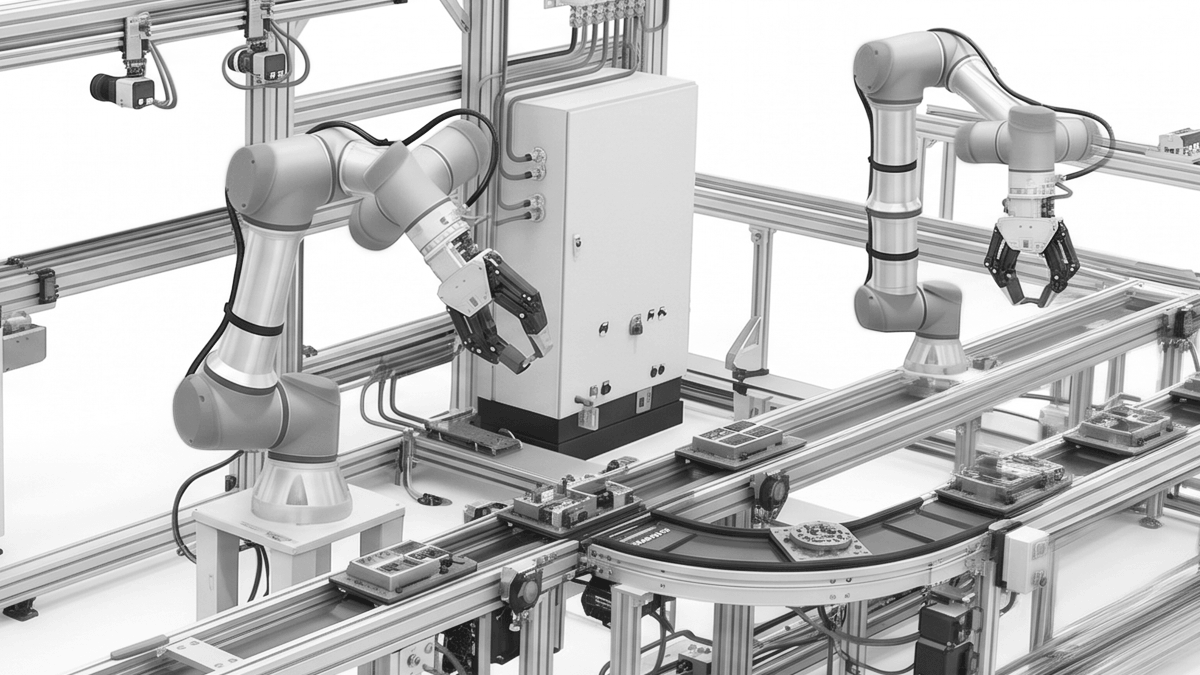
On a single connection, the difference in installation time may be easy to overlook. On a machine with dozens of M12 ports, the repeated steps of aligning, threading, tightening, and checking each connection begin to add up.
Typical connection points- Proximity sensors
- Servo systems
- Industrial cameras
- I/O modules
- Network nodes
- Control modules
Space Constraints and Port Density

A connector can fit on the panel and still be difficult to install. With threaded M12, fingers or tools still need enough room to rotate the coupling nut, which becomes harder as ports move closer together or sit near enclosure walls and neighboring components.
Where this comes up- Compact control cabinets
- Machine vision systems
- Distributed I/O modules
- Robotic equipment
- High-density junction boxes
- Recessed device interfaces
Maintenance and Module Replacement
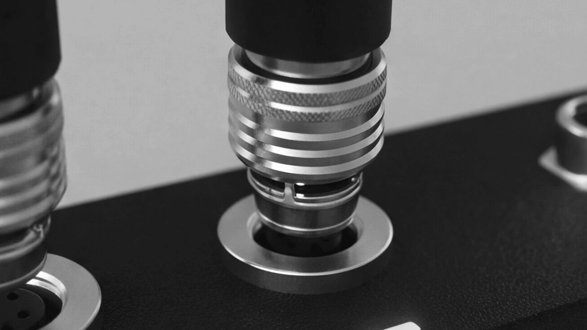
For a connection that is installed once and left in place, a few extra seconds during mating may not matter. The difference becomes more noticeable when cameras, motors, sensors, or I/O modules are replaced as part of regular service.
Common service points- Industrial cameras
- Motors
- Sensor modules
- I/O devices
- Robot end-of-arm tooling
- Field devices
Installation consistency
Threaded M12 may require controlled tightening torque. Push-Pull does not rely on manual rotational torque during mating, which can reduce variation between installers. System validation is still required for sealing, cable routing, strain relief, and interface compatibility.
Compatibility Must Be Verified Item by Item
"M12 Push-Pull" should not be treated as a generic label for every quick-locking M12 interface. Different products may use inner-locking, outer-locking, proprietary, or standardized designs, and a Push-Pull plug must be verified against the actual device-side receptacle.
Some standardized device-side interfaces may support both compatible Push-Pull and conventional threaded M12 connectors, but this should not be treated as a universal characteristic. Actual mating compatibility must be verified at the product and interface level.
Before selection, confirm:
- M12 coding
- Contact count and pin assignment
- Inner-locking or outer-locking design
- Applicable interface standards
- Actual plug-to-receptacle compatibility
- Shielding requirements
- Environmental protection of the fully mated pair
- Cable gauge and construction
- Electrical requirements for signal, data, or power
"M12" defines the basic dimensions and product family of the circular interface—it does not mean every M12 connector will mate with every other.
Which M12 Locking Method Should You Choose?
Both locking methods can support reliable industrial connections. The better choice depends on how the equipment is assembled, serviced, and integrated into the existing M12 architecture.
Best for fast installation, compact layouts, and frequent servicing
- High connection count: Eliminates repeated threading across machines with many M12 connection points.
- Limited installation space: Linear mating reduces the need for rotational clearance around the port.
- High port density: Better suited to closely spaced interfaces and compact equipment layouts.
- Frequent module replacement: Simplifies disconnection and reconnection during servicing.
- Multiple installers: Reduces variation associated with manually applied coupling torque.
- New equipment design: Compatible receptacles can be integrated from the beginning of system planning.
Prioritize assembly efficiency and serviceability.
Best for established systems, fixed installations, and legacy compatibility
- Existing M12 architecture: Avoids unnecessary redesign, validation, and inventory changes.
- Long-term fixed connections: Well suited when connectors are installed once and rarely serviced.
- Customer-specified interfaces: Fits established equipment specifications and approved connector requirements.
- Legacy compatibility: Supports a widely deployed installed base of industrial M12 equipment.
- Adequate installation clearance: Works well where technicians have enough space to thread and inspect the connection.
Prioritize installed-base compatibility and fixed connections.
Connector and Interconnect Design Considerations
The locking method is only one part of the M12 connection system. Also verify:
- Coding and electrical function: Match the interface to the required signal, data, or power function.
- Cable construction: Check shielding, conductor size, flexibility, jacket material, and bend requirements.
- Device-side interface: Confirm the receptacle supports the selected locking method, mounting, and sealing boundary.
- Environmental protection: Evaluate ingress protection on the complete, correctly mated connection system.
- Mechanical integration: Consider vibration, pull forces, strain relief, panel thickness, PCB layout, enclosure space, and service access.
A quick-locking mechanism cannot compensate for an unsuitable cable or poorly integrated device interface.
How ATTEND Supports M12 System Design
ATTEND provides M12 interconnect solutions for industrial automation, robotics, machine vision, control equipment, and other demanding applications. Product-specific locking structures and mating compatibility should be evaluated separately from general M12 Push-Pull characteristics.
Products and design directions include:
- M12 Push-Pull connectors
- Panel-mount M12 interfaces
- Overmolded M12 cable-end connectors
- Field-installable M12 connectors
- Standard and custom cable assemblies
- Connector configurations for signal, data, and power applications
Rather than starting from a single connector specification, ATTEND can help evaluate interface requirements across the cable end, panel end, and system level—supporting equipment manufacturers in choosing the M12 locking method that fits their mechanical layout, assembly workflow, maintenance strategy, and operating environment.
Frequently Asked Questions
Not inherently. Both can provide reliable industrial connections when correctly selected and installed. Push-Pull mainly improves mating speed, access in confined spaces, and consistency by reducing dependence on manual tightening.
Not always. Some device-side interfaces can support both compatible Push-Pull and threaded M12 connections, but universal cross-compatibility cannot be assumed.
For ATTEND products: compatible board-side interfaces can mate with IEC 61076-2-010 Push-Pull cable-side connectors as well as IEC 61076-2-101 conventional threaded M12 cable-side connectors.
Mating and unmating are typically tool-free. Panel mounting, cable preparation, or field termination may still require tools.
Not necessarily. Ingress protection depends on the specific mated pair and installation conditions, so verify the rating of the complete connection system.
Choose the Locking Method from System Requirements
M12 Push-Pull does not replace threaded M12. Threaded interfaces remain well suited to established, fixed installations, while Push-Pull adds value when assembly time, space, or service access becomes a constraint.
The right choice depends on connection count, port density, maintenance frequency, interface compatibility, and environmental requirements—not on locking speed alone.