
Choosing an interconnect solution means evaluating signal requirements, cable architecture, mechanical integration, environmental conditions and long-term reliability at the same time. Industrial drones — UAVs, inspection platforms, survey aircraft and autonomous systems — run several connector families at once — Mini FAKRA, FAKRA, micro-coax, high-speed and floating board-to-board, RF coaxial, M.2, SD / microSD and SIM sockets, USB Type-C, pogo pin arrays and sealed panel-mount interfaces. The right choice comes from evaluating the complete signal path — connector interface, cable assembly, panel entry, board transition — not from a connector specification on its own.
Cameras, GNSS, IMUs, cellular modules, onboard compute and swappable payloads each impose different requirements on the connectors, cable assemblies and board-level interfaces that link them. What makes UAV work harder than ground equipment is the combination behind those requirements: a SWaP budget you have already spent, vibration that never stops, mechanisms that move in flight, and outdoor exposure. This guide works through the airframe subsystem by subsystem — what drives the decision in each, and what changes it.
In This Technical Guide
- Common UAV Interconnect Solutions
- Interconnect Selection Quick Guide
- Camera and Vision Payload Connectivity
- Flight Controller and Edge AI Compute
- GNSS and Wireless RF Connections
- Storage, Memory Cards and SIM
- Battery, Power Distribution and Payload Power
- External I/O, Payload Quick-Release and Charging (incl. ground segment)
- Environmental Protection
- Vibration, Retention and Harness Reliability
- SWaP Considerations
- Engineering Selection Workflow
- Engineering Example
- Key Takeaways
- FAQ
Common UAV Interconnect Solutions
Industrial UAVs draw on several interconnect families depending on signal architecture, environmental exposure, mechanical constraints and integration requirements. The table below is a high-level reference; final selection follows from the actual signal architecture, cable requirements, installation environment and system-level validation.
| Interface | Typical protocol / signal | UAV application | Key characteristics |
|---|---|---|---|
| Mini FAKRA | High-speed coaxial SerDes links * | Multi-camera arrays, dense sensor links | Compact 50 Ω coaxial, multi-channel density, mechanical keying and colour coding |
| FAKRA | GMSL2, FPD-Link, GNSS RF | Single-channel camera links, antenna interfaces | 50 Ω coaxial, colour-coded keying, mature automotive ecosystem |
| Micro-coax | Board-level high-speed data, RF | Short board-to-board camera and antenna runs | Very small footprint for short paths inside the structure |
| High-speed / floating board-to-board | PCIe, high-speed differential, platform-specific | Compute module stack-ups | High density; floating types absorb X/Y misalignment |
| RF coaxial | GNSS (L1/L2/L5), LTE/5G, Wi-Fi | Antenna to transceiver | 50 Ω controlled impedance; frequency and loss follow the cable assembly |
| M.2 | PCIe / NVMe, SATA | Onboard high-speed storage and expansion | 2230 / 2242 / 2280 form factors, M-key / B-key configurations |
| SD / microSD socket | UHS-I (104 MB/s), UHS-II (312 MB/s), SD Express (PCIe / NVMe, 985 MB/s) | Mission data recording and field handover | SDA-compliant, multiple retention mechanisms, card-detect and write-protect options |
| SIM socket / eSIM | LTE / 5G identity module | Cellular link, dual-carrier redundancy | nano-SIM (4FF) in several mechanism types, some with IP-rated variants, plus dual SIM and SIM+microSD combo; or MFF2 solder-down eSIM |
| Power / battery connector | DC high current | Battery swap, distribution, ESC and payload power | Parallel high-current contacts, polarisation, contact sequencing, pre-charge architecture |
| USB Type-C (incl. screw locking) | USB 2.0 / 3.2, USB PD | Service ports, payload data and power | Standard versions rely on friction; locking versions suit in-flight connections |
| Pogo pin | Power, control signals; high speed requires channel design and validation | Payload quick-release, battery swap, charging docks | Spring-loaded surface contact, magnetic self-alignment and break-away, single/multi-pin and sealed variants |
| Sealed panel-mount | Application-specific | Exterior cameras, antennas, charging and service ports | IP-rated sealed interface; protection depends on the complete assembly and test conditions |
| M12 / M8 circular | Industrial Ethernet (including selected M8 SPE configurations), sensor and actuator signals, power (depending on interface and coding) | Ground segment — docking stations, ground control, tethered systems; payload and sensor interfaces on larger platforms | Threaded or push-pull coupling, coding variants, IP-rated sealing, field-serviceable |
* High-speed performance depends on the complete channel design — cable assembly, connector and PCB layout. Refer to product datasheets for rated frequency.
Interconnect Selection Quick Guide
Narrow the direction from system function and installation conditions first, then verify against the complete channel and product specifications.
| System requirement | Interconnect direction |
|---|---|
| High-speed camera links or Power over Coax across the airframe | Mini FAKRA, FAKRA or coaxial camera cable assemblies |
| Dense multi-camera architecture with limited PCB area | Mini FAKRA multi-channel configurations |
| Short board-level camera or sensor interfaces (MIPI CSI-2) | High-speed board-to-board or micro-coax cable assemblies |
| Several structural parts that must align simultaneously | Floating board-to-board connectors |
| GNSS, LTE / 5G and Wi-Fi antenna links | Miniature RF coaxial connectors and cable assemblies |
| Onboard high-speed storage | M.2, form factor chosen from available space |
| Mission data recording with card handover on landing | SD / microSD sockets — bitrate sets the speed class; add card-detect |
| Cellular identity module | nano-SIM socket where numbers are self-managed or swapped in the field; check IP-rated mechanism versions for exposed access; eSIM for sealed systems |
| Battery swap and high-current distribution | High-current contacts / power connectors, selected from peak current, swap frequency and live-mating requirements |
| External USB that must stay connected in flight | Screw-locking USB Type-C cable assemblies |
| Tool-free payload swap, battery swap, autonomous charging | Pogo pin — power and control by default; magnetic self-alignment and break-away worth comparing; sealed versions where exposed; high-speed needs separate design and validation |
| Exterior cameras, antennas, payloads, charging and service ports | Sealed panel-mount interfaces with matched cable assemblies |
| Docking station, ground control, tethered systems, or sensor and payload interfaces on larger platforms | M12 or M8 circular connectors and cable assemblies, selected by coding, signal, power and sealing requirements |
Camera and Vision Payload Connectivity
Industrial UAVs carry RGB, stereo, thermal, multispectral, depth cameras and LiDAR for inspection, survey, navigation and autonomous flight. Each payload pushes a different amount of data down a link that has to survive continuous vibration inside a weight budget you have already spent.
Three conditions narrow the camera link, in this order.
- The protocol sets the channel structure. Interface protocol and data rate determine how many channels the physical layer needs, what impedance they run at and how much loss the link tolerates. What gets validated is the whole path — PCB, connector, cable, connector, receiving PCB — not the connector in isolation.
- Mounting location sets cable length, footprint and mass. On a gimbal or camera head, cable bend behaviour limits mechanical travel directly. In a multi-camera build, each connector's footprint, mating direction and cable exit decide whether the layout closes at all. Fix mounting and routing first, then eliminate whatever will not fit or blow the mass budget.
- Motion and vibration set the retention class. Where cable moves with the mechanism, locking and strain relief are screening criteria rather than bonus features. On a fixed internal link you can relax that and spend the margin on footprint and weight.
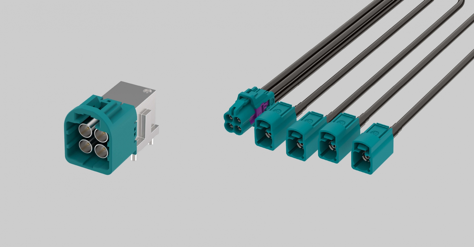
Mini FAKRA Connectors and Cable Assemblies
For the interface fundamentals — 50 Ω multi-channel coaxial, mechanical keying, colour coding — see our Mini FAKRA selection guide. What follows is what changes on an aircraft.
In automotive use, the main argument for Mini FAKRA is packaging space. On a UAV, total cable mass moves from a secondary factor to one of the primary constraints. Every added channel in a multi-camera build brings not just connector footprint but a full coaxial run plus its retention hardware, drawn straight out of the payload budget. So the sequence runs: estimate harness mass from channel count times run length, check it against the SWaP budget, then confirm frequency capability. If the mass does not fit, shorten the routing or move the compute platform before reaching for thinner cable — the loss trade behind that choice is covered in the RF section. One more condition that rarely applies in a vehicle: channels running to the gimbal side need bend life and dynamic bend radius verified against the actual range of motion.
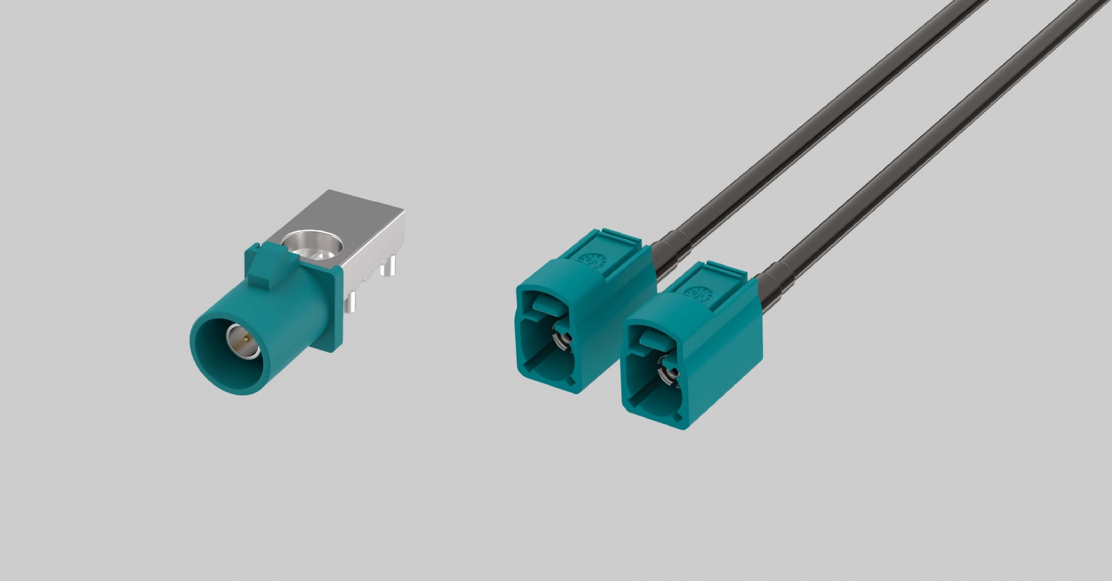
FAKRA Connectors and Cable Assemblies
Interface fundamentals and cable assembly selection are covered in our connector selection guide. The difference on a UAV is which way the trade-off runs. FAKRA's standard envelope is not a problem inside a vehicle, but connector footprint and cable assembly mass accumulate per channel on an aircraft. Platforms with high channel counts or tight space and weight budgets should bring Mini FAKRA or another compact controlled-impedance interface into the comparison. For a single-channel link with room to work — a GNSS antenna interface on a fixed section of the airframe is the typical case — FAKRA remains a mature candidate. The actual decision also takes in existing architecture, qualified cable assemblies, retention requirements and supply ecosystem; channel count alone does not settle it.
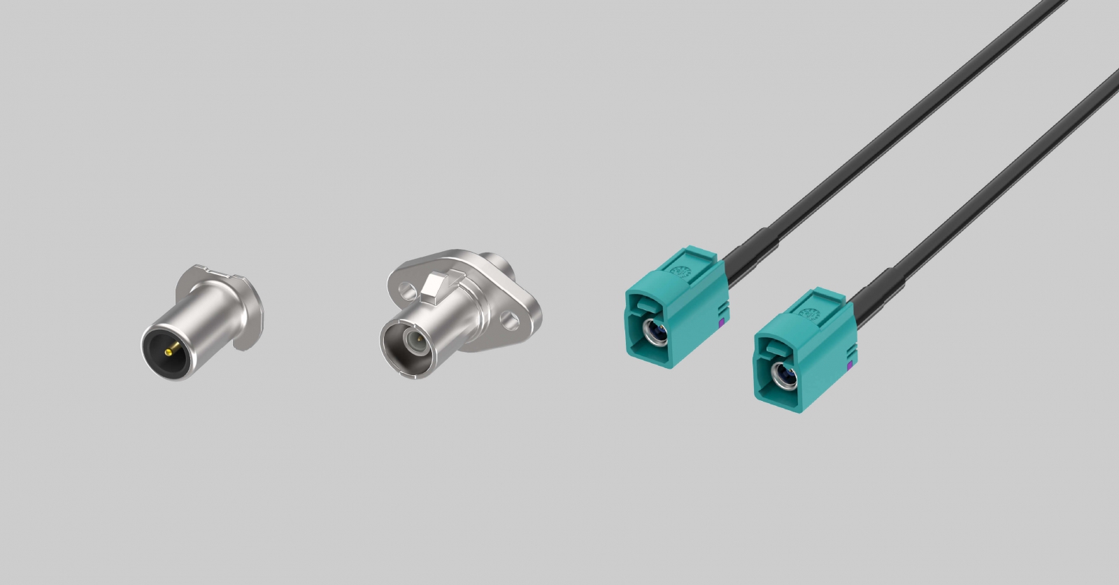
Coaxial Camera Cable Assemblies and Power over Coax
A coaxial camera cable assembly forms the 50 Ω path from camera to compute platform, covering the camera-side connector, the cable and the board transition. Its direct value on a UAV is conductor count: fewer conductors, less harness mass and less routing complexity.
Power over Coax pushes that further. GMSL2 and similar SerDes architectures carry up to 6 Gbps of forward data, control signalling and DC power on one coaxial line, so each camera goes from two runs to one. On a four-camera inspection aircraft that removes four power runs and their retention hardware. The cost is that PoC filter network and grounding strategy move forward into architecture work — power and high-speed signalling share a conductor, and the choice of filter components and the grounding path determine whether supply noise reaches the image channel. That has to be settled early; it is not something you retrofit. Whether it pays depends on the variables: as camera count, average run length and harness mass rise, so does the value of eliminating separate power conductors. With few cameras on short runs, weigh the filter design, BOM and added complexity against the harness mass actually saved.
Related Technical Insight
Connector selection should be evaluated alongside the camera transmission architecture. For a full comparison of GMSL2 and Automotive Ethernet across bandwidth, latency, Power over Coax, routing and scalability, read the GMSL2 vs. Ethernet camera interface selection guide.
Flight Controller and Edge AI Compute
Once perception, image processing and autonomous decisions move onboard, the internal electronics start to look like an edge computing system: flight controller, AI accelerator, camera interface board, IMU, GNSS, storage, cellular module and power management PCB all interconnected in very little space. Board-to-board selection covers pitch (high-speed BTB products commonly sit between 0.35 mm and 0.8 mm), stack height, contact count, data rate, current, mating direction, mechanical tolerance and vibration requirements.
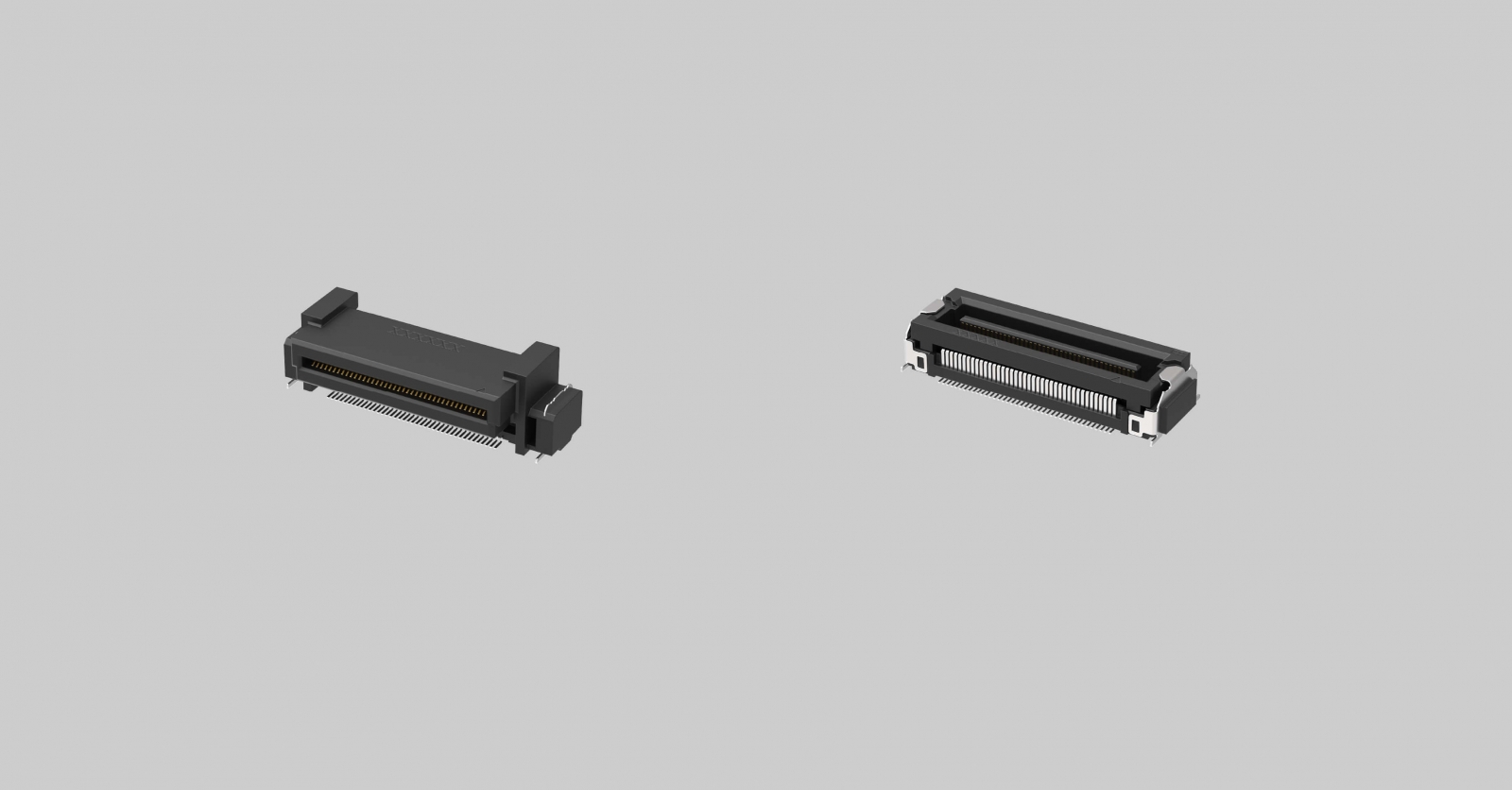
Floating Board-to-Board Connectors
When two or more PCBs are located by different structural parts and the tolerance stack will not close within a rigid BTB's alignment window — a camera head, compute module or sensor assembly that all have to align at once — floating BTB is the answer to that specific problem. Floating connectors allow controlled relative displacement between halves within their specified range, typically ±0.3 mm to ±0.5 mm on general-purpose products, absorbing PCB misalignment, housing tolerance and assembly variation.
Floating range is the first thing to compare. The maximum misalignment your tolerance stack produces has to fall inside the connector's specified float, with margin left over — and a product specified at the upper end of that range absorbs more mechanical variation, which effectively returns tolerance budget to the mechanical design. After float, work through insertion geometry, retention, PCB support and vibration validation on the complete assembly. A floating mechanism does not replace tolerance design.
Related Technical Insight
Edge AI systems deployed at the point of perception have to integrate high-speed imaging and compute alongside vibration, dust, moisture, temperature variation and cable retention. Read the guide to Edge AI connectivity in harsh environments.
GNSS and Wireless RF Connections
A typical industrial UAV runs GNSS, telemetry, Wi-Fi, Bluetooth, LTE/5G, control link and video downlink simultaneously. RF selection is loss budgeting, path by path — not picking one general-purpose RF connector.
- Frequency range. GNSS L1 sits at 1575.42 MHz, L2 at 1227.60 MHz, L5 at 1176.45 MHz, so roughly 1.1 GHz to 1.6 GHz overall. Wi-Fi uses the 2.4 GHz and 5 GHz bands; 5G sub-6 allocations fall below 6 GHz depending on the carrier. The highest frequency on a path sets which connector and cable grades are available.
- Impedance. UAV RF systems run predominantly at 50 Ω characteristic impedance, held consistently across the path to limit reflection and added loss.
- Cable length and type. Coaxial attenuation rises with frequency, and among similar constructions a smaller cable generally attenuates more — but actual attenuation comes from conductor loss, dielectric loss and construction together, and there is no conversion rule that transfers between cable types. So cable selection does not start from diameter. Establish the allowable insertion loss for that path at its highest operating frequency — a passive GNSS antenna is the sensitive case, where cable and connector loss ahead of the LNA reduces the carrier-to-noise margin available at the receiver — then take each candidate cable's dB/m at the operating frequency from its datasheet, multiply by actual run length, and screen out whatever fails the budget. When nothing passes, there are three options: a lower-loss cable, a shorter route, or a different antenna position.
- Retention. RF interfaces under vibration rarely fail by pulling apart. They fail through micro-motion at the contact interface, which produces intermittent loss variation — sporadic signal degradation in flight that is very hard to reproduce on the bench. The first tie-down point after the connector determines how much mechanical load reaches the contact; placing it as close to the connector as the design sensibly allows does more than upgrading to a stronger connector afterwards.
- Antenna placement. Plan antenna position and connector selection together. Moving an antenna away from the processor, motors or other noise sources usually lengthens the cable, and cable length adds loss. Treat the RF path as one system: antenna, cable, connector, board transition, RF circuit.
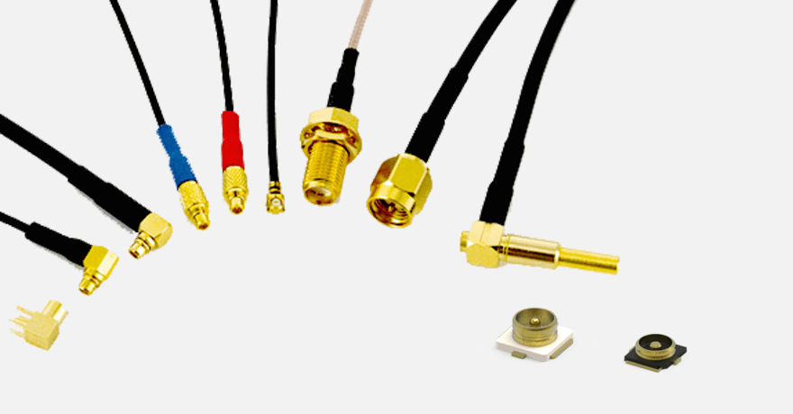
RF Coaxial Connectors and Cable Assemblies
Select miniature RF coaxial connectors and matching cable assemblies from frequency, run length, antenna position and allowable loss. Board-side and panel-side interface styles follow from the mechanical layout and sealing requirements.
Storage, Memory Cards and SIM
Raw imagery volume on inspection and survey missions sets the capacity and sustained write rate the aircraft needs. Three module interfaces come up: M.2 high-speed storage, removable SD / microSD cards, and the SIM for cellular. They fail differently, so they select differently.
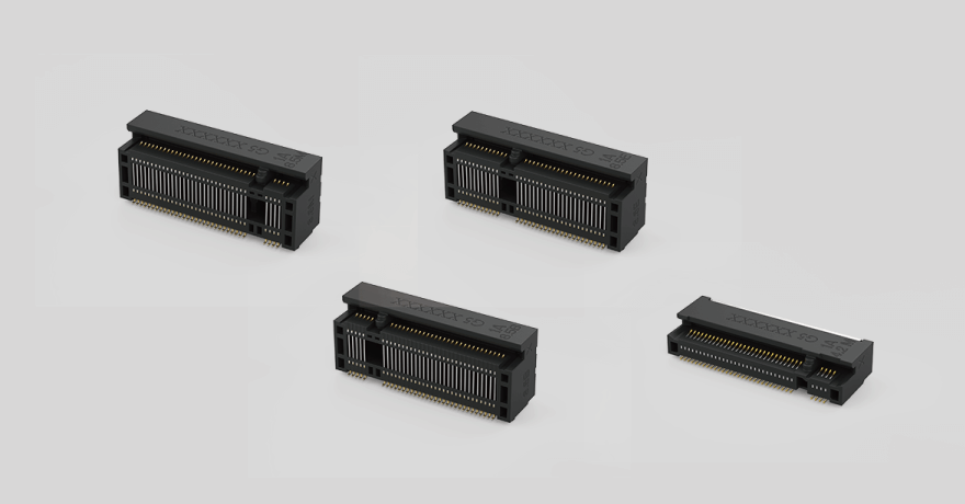
M.2 High-Speed Storage Sockets
M.2 2230, 2242 and 2280 map to different mechanical envelopes; M-key runs PCIe lanes (Gen3 x4 gives roughly 32 Gbps theoretical bandwidth) while B-key covers SATA or PCIe x2 configurations.
The primary UAV risk here is mechanical. A 2280 card secured by a single screw at one end is a cantilever, and vibration concentrates stress at the gold fingers and solder joints. A heatsink adds mass and changes the module's dynamic behaviour along with it. Options worth evaluating include a shorter card (2230 or 2242), added module support or suitable damping, and vibration assessment on the actual assembly once thermal and mounting design are complete — resonance behaviour comes from mass, stiffness, mounting and geometry in combination, so it has to be measured on the assembly rather than predicted from any one of them.
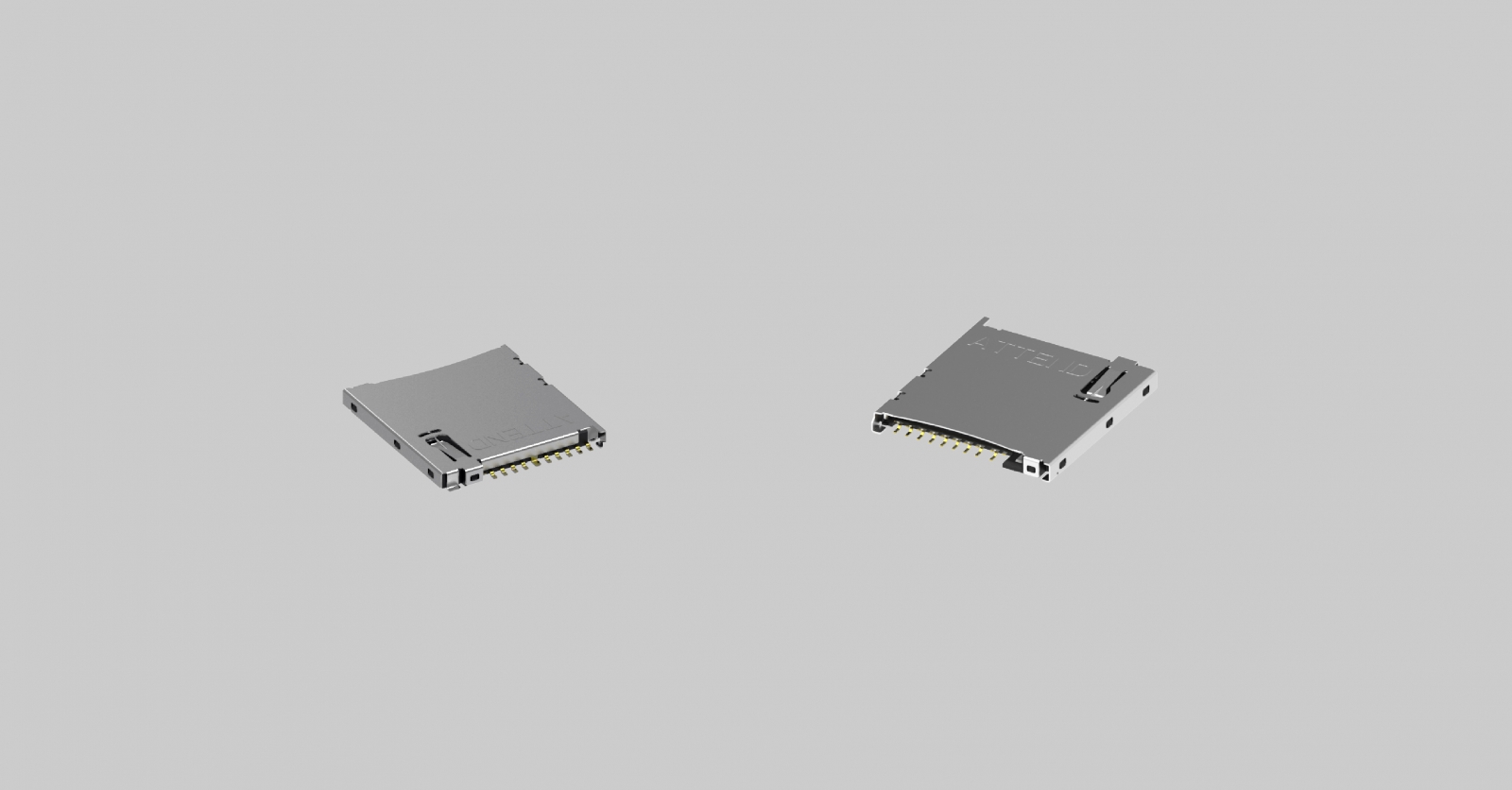
SD / microSD Memory Card Sockets
Workflows that hand over data by pulling the card on landing, or that have field crews swap media, need removable storage. Derive the speed requirement from bitrate rather than from a resolution label: "4K" says nothing definitive on its own, because codec, bit depth, frame rate, compression and camera count all move the number, and RAW or lightly compressed machine vision data can sit an order of magnitude above H.265 recording. Sum the sustained output bitrate of every source writing at once, add filesystem and buffering margin, and match the result to a Video Speed Class (V30, V60 and V90 guarantee 30, 60 and 90 MB/s minimum sustained write) or a higher interface class.
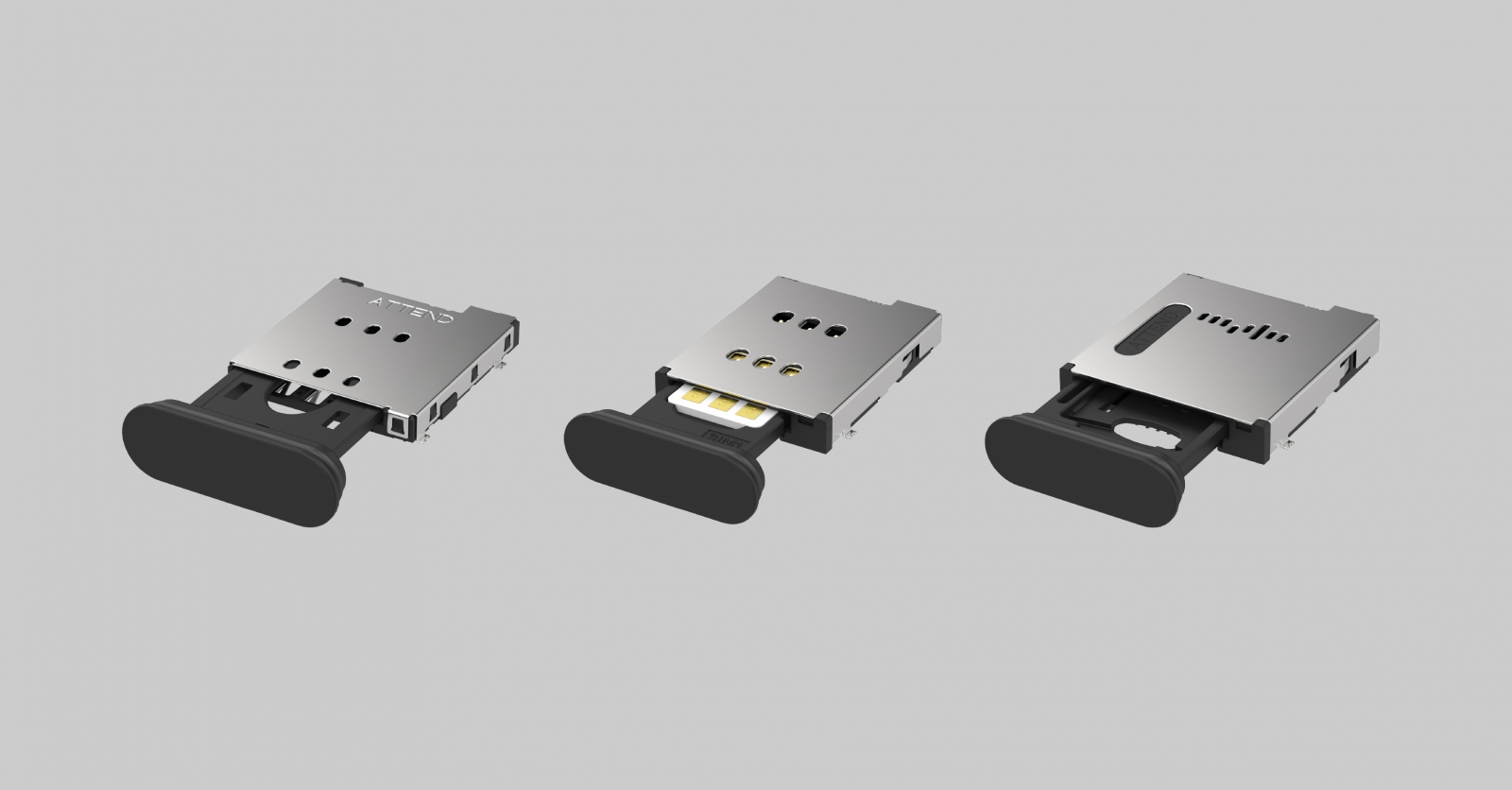
SIM Sockets and eSIM
Cellular links need a SIM, and the two routes — physical nano-SIM (4FF, 12.3 × 8.8 mm) in a socket, or solder-down eSIM (MFF2) — divide on one question: who manages the subscription, and how often does it change? Fleets deployed across carriers or countries, subscriptions managed by the customer or the operator, troubleshooting that involves swapping a card in the field — a physical socket matches that operating model directly, since changing carrier means changing a card rather than depending on remote provisioning. eSIM removes a mechanical opening and a retention mechanism, which suits sealed systems shipped as a closed unit on fixed tariffs; the cost is that subscription management moves entirely into software and contracts, and carrier changes, fleet-scale transfers and roaming policy all need the corresponding systems behind them.
Battery, Power Distribution and Payload Power
The DC high-current path from battery to distribution board, ESCs, compute platform and payload behaves differently from signal interfaces. Current, thermal rise, mating frequency and inrush need to be treated as part of the power architecture rather than as connector specifications in isolation.
Current & Thermal
Continuous current, peak current and temperature rise determine contact count and conductor size. Verify the actual parallel configuration rather than multiplying a single-contact rating.
Battery Swap
Frequent replacement moves mating-cycle life, polarisation and blind-mate guidance into the primary selection criteria.
Live Mating
Bus capacitance can create inrush and arcing. Where live mating is required, evaluate pre-charge or staged-contact architecture with the battery-management system.
Power + Data
Separate interfaces simplify isolation and EMI control. A hybrid interface saves space and one mating action, but power noise and high-speed signalling must be managed together.
External I/O, Payload Quick-Release and Charging
Not every connector on a UAV is live in flight. Some handle firmware updates, data download, debug, charging, payload configuration and field service. Another group has to mate without a cable and without a plugging action at all — payload quick-release, battery swap contacts, autonomous charging docks. The two groups select differently.
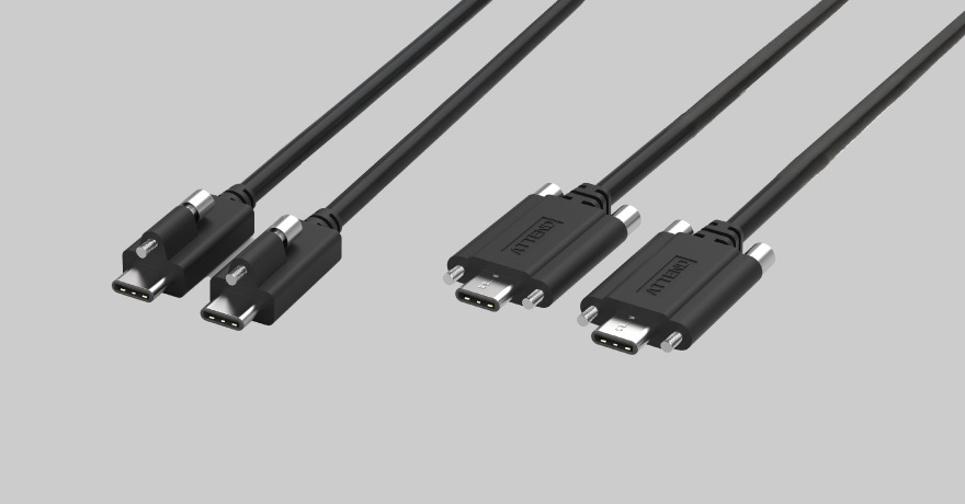
USB Type-C Screw-Locking Cable Assemblies
USB Type-C carries 480 Mbps (USB 2.0) up to 10 Gbps and beyond (USB 3.2) depending on version, and the interface specification calls for 10,000 mating cycles — so for general service and configuration use, mating durability is rarely the limiting factor. Retention is. A standard Type-C connector holds by friction alone with no mechanical lock, so cable strain or sustained vibration can disconnect it. That splits the decision cleanly: for a service port used on the ground and unused in flight, focus on the dust cap and unmated sealing. For an interface that has to stay connected in flight — a payload drawing power or passing data over USB-C — use a screw-locking version or add mechanical retention. Do not rely on friction.
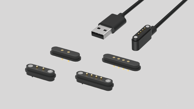
Pogo Pin Connectors and Cable Assemblies
Pogo pins make contact through spring-loaded plungers against a mating surface. You set the payload down rather than plug it in — no cable, blind mating tolerated, alignment handled by guide posts or magnets. That combination makes three UAV situations worth evaluating: tool-free payload swaps, where field crews change sensor modules repeatedly; battery swaps, where fleet rotation drives mating counts well past what a typical connector is specified for; and drone-in-a-box charging, where the aircraft lands and contact pads do the rest, with touchdown error absorbed by pad area and mechanical guidance.
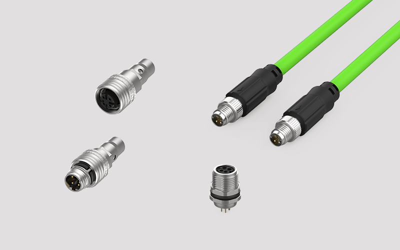
M12 and M8 Circular Connectors
Circular industrial connectors are a poor fit inside a weight-critical airframe — a threaded metal shell costs more mass than a UAV interconnect budget usually allows. They belong to the parts of the system where that constraint does not apply.
Environmental Protection
An outdoor UAV does not mean every connector needs the same IP rating. Draw the sealing boundary for each interface first: where a connector sits entirely inside a sealed housing, the housing provides protection and the connector needs no rating of its own. Where the connector forms the boundary, it does.
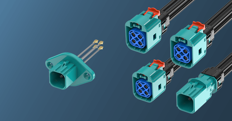
Sealed Panel-Mount Interfaces
Exterior cameras, removable payloads, outdoor antennas, charging and service ports need sealed interfaces. An IP rating is not a catalogue number to compare directly — IP67 immersion and IPX9K high-pressure washdown are different tests, and the conditions behind each rating are covered in the IP rating article below. What this article adds are the three UAV-specific checks: whether the rating holds mated or unmated (service ports and removable payloads spend most of their life in one state or the other, so check the state that applies); whether it covers the connector interface, the cable assembly or the complete housing; and whether panel openings, cable exits or the assembly process introduce a new ingress path. One is enough to cost the subsystem the protection it was specified for, which is why environmental protection gets assessed at system level.
Related Technical Insight
For a full comparison of IP67, IP68 and IPX9K under dust, immersion and high-pressure washdown conditions, read the IP rating guide.
Vibration, Retention and Harness Reliability
Motors, propellers, takeoff and landing, attitude changes and payload movement all load connectors and cable assemblies, continuously or in bursts. Vibration resistance is generally qualified by methods such as IEC 60068-2-6 (sinusoidal) and IEC 60068-2-64 (random).
Vibration rarely kills a connector by pulling it apart. It works through fretting: contact surfaces sliding against each other over micrometre distances, oxidising, and driving contact resistance up intermittently. What that looks like in service is the worst category of fault — occasional signal dropouts in flight, and every measurement normal once the unit comes back for testing.
The countermeasures have an order, and it does not invert. Eliminate relative motion at the interface with positive locking first: no relative motion, no fretting. Then fix the harness so vibration loads never reach the contact. Contact normal force and fretting-resistant plating come last, after the first two are done. The classic symptom of working that order backwards is a higher-specification connector with no improvement in failure rate, because the harness still moves exactly as before.
Cable mass and harness routing are the parts most often underestimated. A very light miniature connector carrying a long or poorly secured cable still sees vibration load working continuously on its termination and PCB mounting. Harness design belongs alongside connector selection, not after PCB layout closes.
SWaP Considerations
UAV designs live under SWaP constraints, but the unit of comparison has to be right: compare the connector plus cable plus retention and strain-relief hardware as one assembly, not connector size against connector size. Weight saved by shrinking a connector often comes back through the loss compensation thinner cable demands — a heavier cable or a shorter path — or through the extra hardware needed to secure it. The reverse holds too: a slightly larger connector with integrated locking and strain relief can eliminate a set of clamps and brackets. SWaP optimisation applies to the whole interconnect assembly, not the dimension on the datasheet.
Engineering Selection Workflow
Selection starts from system requirements rather than a connector catalogue. This sequence works for narrowing options early in a new programme.



Step 1 — Signal requirements
- What signal type and protocol is being carried?
- What operating frequency or data rate?
- What impedance has to be maintained?
- Does power share the same conductor (PoC or equivalent)?
Step 2 — Location and environment
- Is the interface internal, external, inside a sealed housing, on a removable payload, on a moving gimbal, or accessible for field service?
- What is the operating temperature range?
- Is it exposed to vibration, shock or repeated mating?
- Is sealing required, and to what level for the actual installation?
Step 3 — Mechanical and cable assembly requirements
- What space and mass budget does the connector plus cable assembly have?
- Cable type, routing path, length, minimum bend radius, shielding, strain relief?
- Overmoulding, panel sealing or a custom cable assembly?
- Mating direction, assembly tolerance, retention requirements?
- How often does this get serviced or replaced, and how?
Step 4 — System-level validation
- With the connector type set, validate the cable assembly, PCB transitions, board-side interfaces, shielding strategy, routing and installation conditions together as one signal path. A connector specification does not confirm system-level performance.
- Can production staff assemble it repeatably? Does it need special tooling? How do you inspect mating state and assembly quality?
Engineering Example: Multi-Camera AI Inspection UAV
Consider an industrial UAV designed for infrastructure inspection. The system includes four high-resolution cameras, GNSS, an IMU, an onboard AI computing platform, SSD storage, removable microSD storage for mission data and field delivery, LTE/5G connectivity, a detachable inspection payload, and an external service interface. Each interconnect path can be evaluated separately:
UAV Interconnect Architecture
Hover over each subsystem to explore its key interconnect considerations.
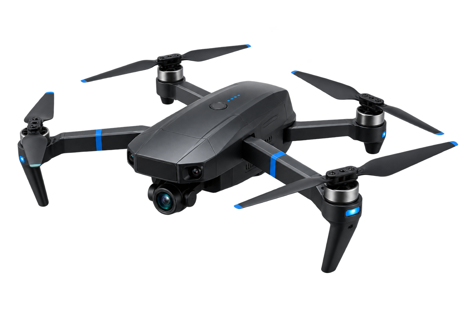
Bandwidth, routing distance and PCB area drive the camera-link architecture.
Data rate, board spacing and assembly tolerance drive the board-level interface.
Storage workflow, vibration and removable-media access shape the storage interface.
Field access, antenna location, cable length and allowable RF loss drive the connectivity path.
Continuous current, peak current, inrush and mating conditions drive the power interface.
Accessibility, protection and retention depend on whether the connection is ground-only or used in flight.
Blind mating, repeated replacement and positioning tolerance drive the quick-release interface design.
Key Takeaways
- UAV connector selection starts from signal, mechanical, environmental and system-validation requirements rather than a connector specification; high-speed and RF paths get validated as complete channels.
- Different subsystems map to different connector families — camera links, board-level interconnect, RF antennas, storage and card sockets, power, and external I/O each fail differently and select differently. The ground segment — docking stations, control equipment, tethered systems — selects on industrial rather than airborne criteria.
- Three conditions amplify everything on a UAV: SWaP, continuous vibration and outdoor exposure. Common risks include harness mechanical load, contact fretting, module retention, ingress paths and live mating — all verified on the complete assembly rather than the individual part.
- Decisions that depend on product specifications — frequency, float range, plating, socket mechanisms, IP test conditions — get verified against current product documentation and qualification data.
FAQ
No single connector type covers an entire aircraft. Camera links, board-level interconnect, RF antennas, storage and card sockets, power distribution and external I/O each map to a different connector family, and the choice follows that path's signal type, available space, mass budget, vibration conditions and environmental exposure. Several interface types coexisting on one UAV is the normal outcome, not a design flaw.
It depends on the camera interface. Board-level interfaces such as MIPI CSI-2 use high-speed board-to-board or micro-coax cable assemblies. Where GMSL2 or similar SerDes carries data across the airframe, use a controlled-impedance coaxial solution — FAKRA is worth comparing first on a single-channel link with space to work, and Mini FAKRA becomes the main candidate where channels are many and PCB area is tight. High-speed links get validated as a complete channel; connector size alone does not decide it.
Where the architecture calls for compact, controlled-impedance or multi-channel coaxial connections, Mini FAKRA belongs in the comparison. Whether it fits still depends on the actual frequency, data rate, cable, retention, vibration, mass and environmental requirements — it is not a universal UAV standard.
Both are 50 Ω coaxial interfaces. On a single-channel link with room in the structure, FAKRA brings a mature ecosystem and wide cable choice. In a dense multi-camera build with limited PCB area, Mini FAKRA provides multi-channel configurations in a smaller footprint, which can reduce connector footprint and overall packaging burden; actual cable assembly mass still depends on construction, length and configuration. Channel count and available space decide this, not bandwidth.
Where compact compute, camera or sensor modules carry PCB and mechanical assembly tolerance, a floating connector absorbs alignment variation within its specified range (typically around ±0.3 mm to ±0.5 mm ), reducing added mechanical stress. The float range still has to work with the overall tolerance design and be confirmed by vibration validation.
Start from speed requirement and compatibility. Sum the sustained bitrate of every source writing at once to get the minimum sustained write requirement, then match it to UHS-I, UHS-II or SD Express class. An SDA-compliant socket behaves predictably in card compatibility and recognition. Choose the mechanism type from mounting position and swap method, and confirm suitability against the platform's vibration conditions. Add a card-detect switch so the flight controller confirms the card before takeoff — considerably cheaper than discovering after landing that nothing recorded.
It follows the operating model. Fleets deployed across carriers or countries, with subscriptions managed by the customer and cards swapped in the field, suit a physical nano-SIM socket — hinge or tray internally, IP-rated mechanism versions where cards are accessed through the housing, dual SIM for redundancy on long-endurance missions. Sealed systems on fixed tariffs can evaluate eSIM (MFF2 solder-down), which removes a housing opening and a retention mechanism; subscription management then moves into software and contracts, and fleet-scale transfers and troubleshooting need the systems to match.
Not all of them. A connector entirely inside a sealed housing is protected by the housing; a connector that forms the boundary needs a rating. For exposed interfaces, confirm the complete mated assembly, cable exit, panel sealing and the actual test conditions — IP67 immersion and IPX9K washdown are different tests, covered in the IP rating article — rather than reading the number on the connector alone.
It works well for service, data transfer and payload configuration. For general service use, the 10,000-cycle class mating durability specified for the interface is rarely the limiting factor; retention, strain relief and sealing are. A standard connector holds by friction, so any interface that must stay connected in flight needs a screw-locking version or separate mechanical retention.
These are situations worth evaluating pogo pins for: no cable, blind mating tolerated, alignment from guide posts or magnets, matching how field crews and autonomous docking actually work. Magnetic versions also break away under load, so the interface separates instead of transferring force into the structure or harness, and sealed IP-rated versions are available for exposed positions. Confirm that stroke covers vibration displacement and positioning tolerance, and size parallel pin count from the per-pin current rating. Power and control are the default use; high-speed data requires contact geometry, pin arrangement and the complete channel to be designed and validated for the target rate, otherwise route it separately.
Three conditions. Continuous and peak current size the contact count and conductor cross-section, with temperature rise verified against the derated rating in the actual parallel configuration. Swap frequency sets mating cycle life, polarisation and blind-mate guidance requirements. And whether the connector mates live determines the need for a pre-charge or staged-contact architecture — a connector's current rating does not cover hot-plug inrush and arcing. Size voltage drop and thermal design against end-of-life contact resistance.
No. The unit of comparison for SWaP is the connector plus cable plus retention and strain-relief hardware. Weight saved on the connector can return through loss compensation on thinner cable or the extra hardware needed to secure it, while a slightly larger connector with integrated locking and strain relief may eliminate a whole set of clamps and brackets.