
Selecting the right interconnect solution requires evaluating signal requirements, cable architecture, mechanical integration, environmental conditions, and long-term system reliability.
Automotive, industrial, and intelligent systems use a range of connector interfaces, including FAKRA, Mini FAKRA, HSD, HS-MTP, M12, M8, USB-C, OBD2, and sealed panel-mount solutions. The right choice depends on evaluating the complete signal path, including connector interfaces, cable assemblies, panel entries, and board-level transitions, rather than a connector specification alone.
Connector and cable assembly selection can affect signal integrity, EMI performance, mechanical retention, environmental protection, and long-term system reliability. Cameras, radar modules, LiDAR, communication devices, and computing platforms each impose different requirements on the connectors, cable assemblies, and board-level interfaces that link them together.
In This Technical Guide
- Common Interconnect Solutions
- Interconnect Selection Quick Guide
- Automotive Camera Connector Interfaces
- Connectors for ADAS and Sensor Systems
- Vehicle Diagnostics and In-Cabin USB Interfaces
- Environmental Design Considerations
- Industrial, Robotics, and Edge AI Connectivity
- High-Speed Signal Integrity Design
- Engineering Selection Framework
- Key Takeaways
- FAQ
Common Interconnect Solutions Used in Modern Intelligent Systems
Modern automotive, robotics, and intelligent systems rely on a range of connector and interconnect solutions depending on signal architecture, environmental requirements, mechanical constraints, and system-level integration needs.
The following comparison provides a high-level reference for interconnect solutions used across camera systems, ADAS platforms, industrial automation, robotics, and edge AI applications. Final selection should be based on the required signal architecture, cable requirements, installation environment, mechanical constraints, and system-level validation.
| Connector Type | Typical Protocol / Standard | Typical Applications | Key Characteristics |
|---|---|---|---|
| FAKRA | GMSL2 / GMSL3, FPD-Link III / IV * | Automotive camera, GPS, V2X antenna, telematics | 50-ohm coaxial interface, color-coded keying, mechanical polarization, and automotive-oriented configurations |
| Mini FAKRA | GMSL2 / GMSL3, FPD-Link III / IV * | High-density camera arrays, ADAS, compact sensor links | Compact 50-ohm coaxial interface, high-density packaging, mechanical keying, and high-frequency configurations |
| Coaxial Camera Connectors | GMSL2 / GMSL3, FPD-Link III / IV * | Camera-to-ECU coaxial links across automotive and embedded vision systems | Product family covering FAKRA, Mini FAKRA, and sealed panel-mount variants for camera signal transmission |
| HSD | LVDS / USB 2.0 / 100BASE-T1 | Infotainment display, rear camera, driver monitoring | Four-contact 100-ohm differential interface with locking mechanism |
| HS-MTP | Multi-gig automotive Ethernet (1000BASE-T1+), high-speed SerDes | ADAS, high-resolution camera systems, display connections | Modular 100-ohm differential design, shielded or unshielded, with mechanical coding |
| OBD2 | CAN (ISO 15765), ISO 9141, SAE J1850 over SAE J1962 interface | Vehicle diagnostics, telematics, fleet management, data loggers | 16-pin standardized interface for diagnostic access |
| USB-C | USB 2.0 / 3.2, USB Power Delivery | In-cabin infotainment, diagnostics, AGVs, commercial vehicles, industrial HMI | Data transfer and power delivery in one interface, with screw-locking and sealed variants for industrial environments |
| M12 / M8 Circular | Industrial Ethernet (D / X-coding), sensor and actuator signals (A-coding), fieldbus (B-coding), power (S / T / L-coding) | Industrial vision, robotics, machine automation, compact sensors | Threaded or push-pull coupling with coding variants and sealing options |
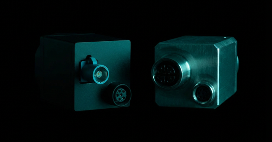
| Waterproof Panel-Mount | Application-specific interface | Exterior camera, outdoor antenna, sealed enclosures | Sealed panel-mount interface with IP-rated protection for outdoor or enclosure applications |
| Floating Board-to-Board | Board-level interconnect | Industrial automation, automotive electronics, AI/edge computing, test equipment | Floating mechanism for X/Y misalignment and board stacking tolerance |
* High-speed performance depends on the complete channel design, including cable assembly, connector, and PCB layout. Refer to product datasheets for verified frequency ratings.
Interconnect Selection Quick Guide
This quick guide helps narrow the initial interconnect direction based on the system function, signal architecture, installation environment, and integration requirements. Final selection should still be verified against the complete channel design and product specifications.
| System Requirement | Interconnect Direction |
|---|---|
| High-speed automotive camera links or Power over Coax architectures | FAKRA, Mini FAKRA, or coaxial camera connectors and cable assemblies |
| High-density multi-camera ADAS architectures | Mini FAKRA and high-density coaxial interconnect solutions |
| Differential video, displays, or automotive Ethernet links | HSD, HS-MTP, or other compatible shielded differential interconnects |
| Exterior cameras, antennas, sensors, or sealed enclosure feedthroughs | Waterproof panel-mount interfaces with application-matched cable assemblies |
| Industrial Ethernet, sensors, actuators, and distributed I/O | M12 or M8 connectors and cable assemblies selected by coding, signal, power, and sealing requirements |
| Secure USB data and power connections in mobile or vibration-prone equipment | Automotive USB Type-C connectors and cable assemblies, or screw-locking USB-C cable assemblies |
| Compact internal board integration with mechanical tolerance requirements | Floating board-to-board connectors |
| Vehicle diagnostics, telematics, fleet management, and data logging | OBD2 connectors and cable assemblies |
Automotive Camera Connector Interfaces
Camera systems in vehicles and intelligent platforms require connectors that support reliable high-speed data transmission, stable mechanical mating, and, in some architectures, simultaneous power delivery over the same cable.
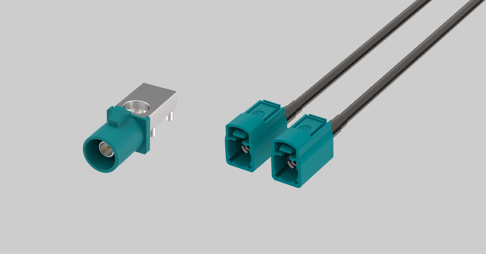
FAKRA Connectors & Cable Assemblies
FAKRA connectors and cable assemblies are widely used in automotive RF and high-speed camera applications. The interface is commonly specified as a 50-ohm system, with frequency performance depending on the selected connector, coaxial cable assembly, and complete channel design.
FAKRA interconnect solutions use color-coded, mechanically keyed housings to reduce mismating risk in multi-interface vehicle systems. Cable assemblies should be selected for the required routing length, shielding, bend radius, termination method, and installation environment. Typical applications include surround-view cameras, ADAS front cameras, GPS and telematics antennas, and selected V2X communication interfaces.
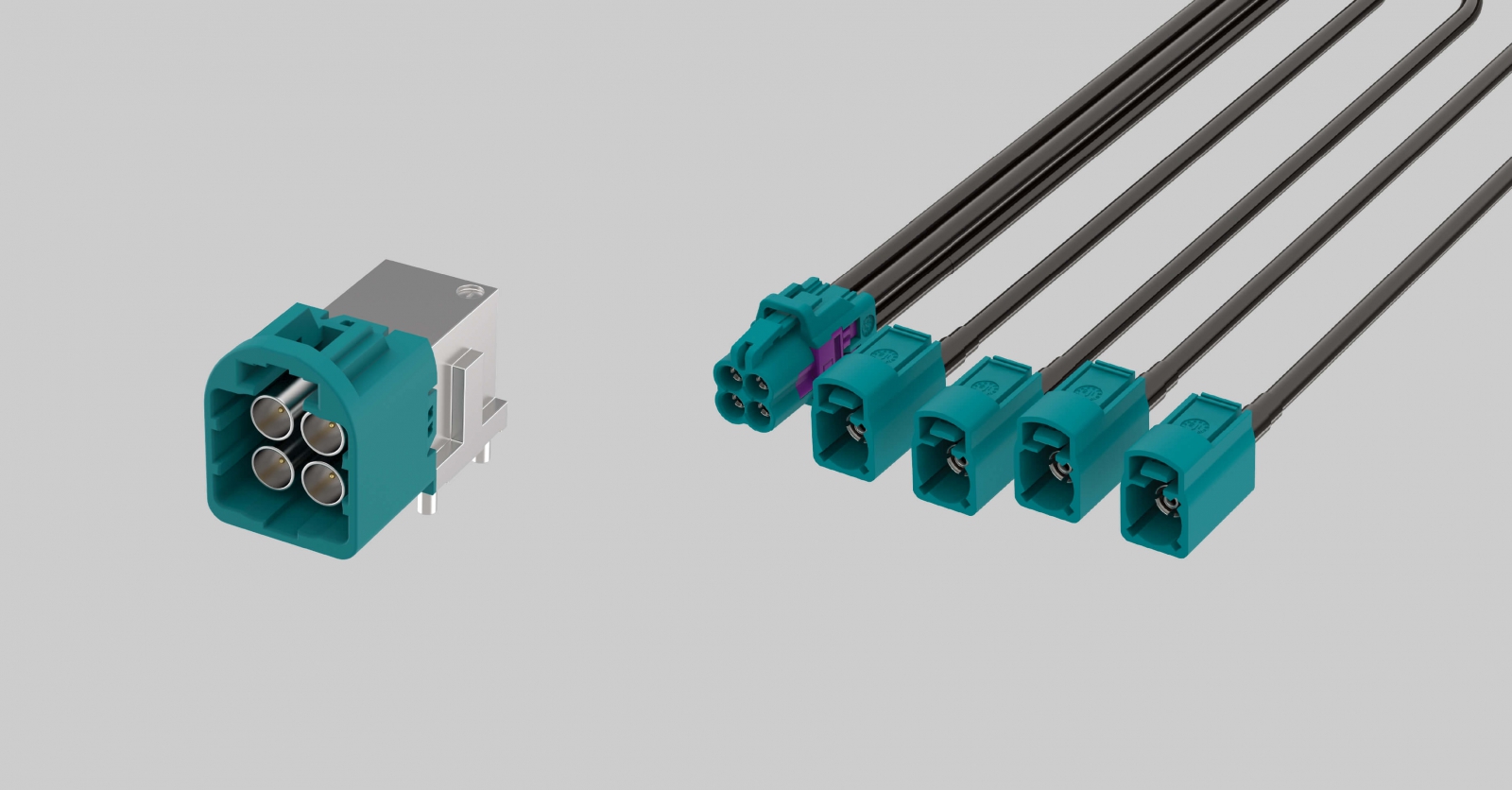
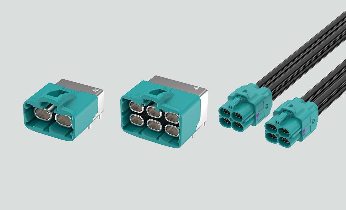
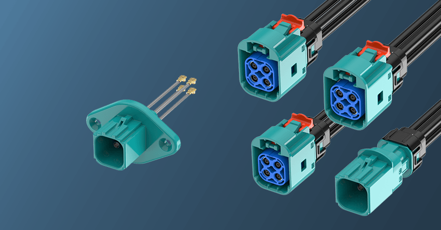
Mini FAKRA Connectors & Cable Assemblies
Mini FAKRA connectors and cable assemblies are designed for high-density automotive connectivity. The compact coaxial system retains mechanical keying and color-coding while reducing the packaging space required for multi-channel camera and sensor architectures. Electrical performance, size reduction, cable configuration, and frequency capability depend on the selected product series and configuration.
Mini FAKRA interconnect solutions are commonly used in high-density camera and sensor architectures where multiple channels must be routed within limited space, especially in ADAS platforms with increasing camera count. Cable assembly selection should account for channel count, routing length, shielding, and mechanical integration.
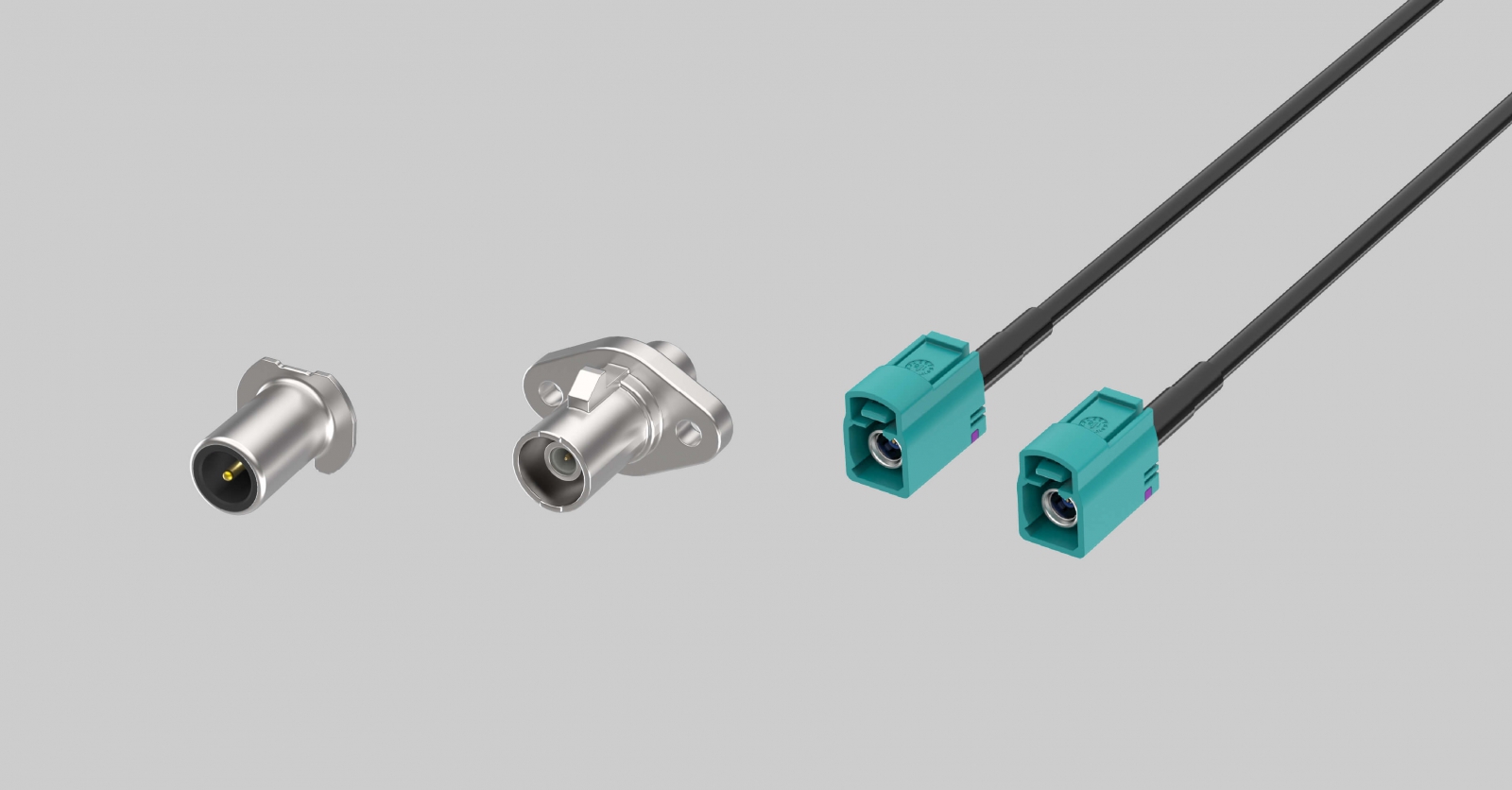
Coaxial Camera Connectors & Cable Assemblies for Power over Coax
Coaxial camera connectors and cable assemblies provide the RF interconnect between camera modules and vehicle processing platforms. Depending on the system architecture, the complete interconnect may include the camera-side connector, coaxial cable assembly, panel interface, ECU-side connector, and board-side transition at the processing unit.
Many automotive camera systems use Power over Coax architectures, allowing DC power and high-speed video data to share the same coaxial cable. PoC capability depends on the complete channel design, including the SerDes chipset, PoC filter network, cable assembly, connector interfaces, PCB transitions, and grounding strategy.
Channel Design Note
Interconnect selection should be evaluated against the complete channel, including the connector, cable assembly, PCB transition, shielding design, cable routing, and application environment.
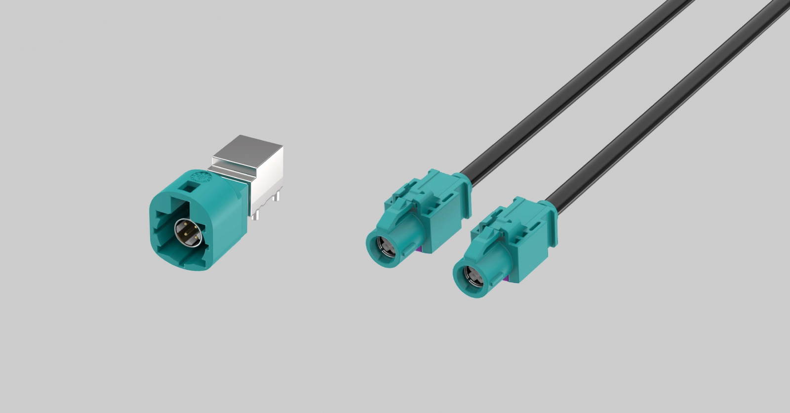
HSD Connectors & Cable Assemblies
HSD connectors and cable assemblies are shielded differential interconnect solutions commonly used in automotive systems for applications such as LVDS, infotainment displays, rear-view cameras, driver-monitoring systems, and selected automotive Ethernet links. Final selection should consider the required protocol, cable routing, shielding continuity, cable construction, and mating configuration.
Related Technical Insight: Camera Transmission Architecture
Connector selection should be evaluated together with the camera transmission architecture. For a deeper comparison of GMSL2 and Automotive Ethernet across bandwidth, latency, Power over Coax, cable routing, and system scalability, read Engineer’s Selection Guide: GMSL2 vs Ethernet Camera Interfaces.
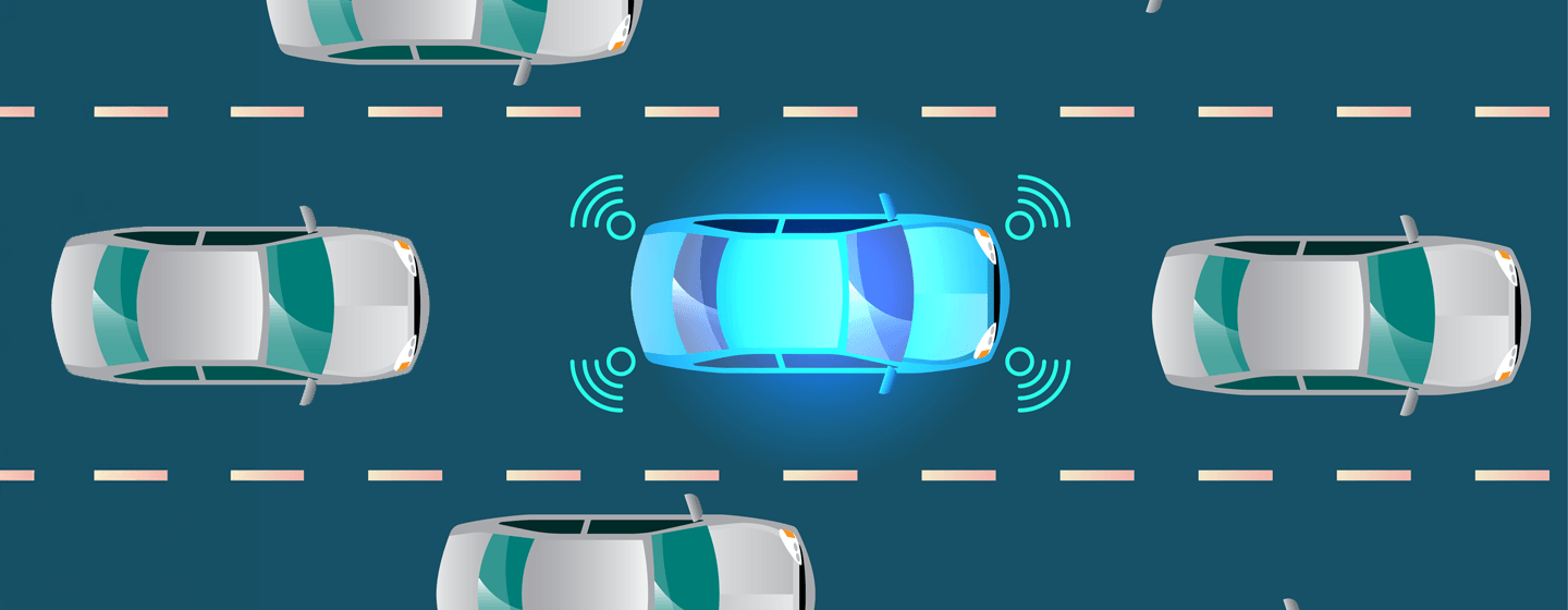
Connectors for ADAS and Sensor Systems
Advanced driver assistance systems integrate cameras, radar, LiDAR, ultrasonic sensors, and communication modules into a unified perception architecture. Each interface has distinct connector requirements based on signal type, data rate, shielding needs, environmental exposure, and packaging constraints.
RF Antenna and Radar Interfaces
Radar modules, GNSS antennas, and V2X communication systems require RF interconnects that maintain controlled impedance, shielding continuity, and stable performance across the operating frequency range. Connector and cable assembly requirements vary by signal type, module architecture, cable routing, and environmental exposure.
HS-MTP Connectors & Cable Assemblies
HS-MTP connectors and cable assemblies are used in selected automotive Ethernet, ADAS, high-resolution camera, and display applications. Available solutions may include connector interfaces, shielded cable assemblies, and application-specific configurations for high-speed differential signal routing. Signal performance, shielding configuration, cable construction, and qualification requirements depend on the selected product series and system architecture.
Multi-Camera Surround-View Systems
Surround-view systems connect multiple cameras around the vehicle perimeter to a central processing ECU. In these architectures, cable routing, channel loss variation, connector mating consistency, shielding continuity, channel-to-channel performance, and serviceability can affect link margin, synchronization strategy, and long-term system consistency.
Example surround-view architecture connecting multiple vehicle cameras to a central ECU through coaxial cable assemblies.
Related Technical Insight: Multi-Camera Vision AI Architecture
Multi-camera system design extends beyond an individual connector specification to data aggregation, synchronization, signal integrity, compute-platform integration, and system scalability. Learn more in Vision AI Architecture Design: From Sensor to Compute in Multi-Camera Systems.
Vehicle Diagnostics and In-Cabin USB Interfaces
Beyond camera and sensor links, automotive systems also include diagnostic, service, infotainment, and user-facing connectivity interfaces. These connectors serve different functions from RF coaxial and differential camera interfaces, but remain part of the overall vehicle connectivity architecture.
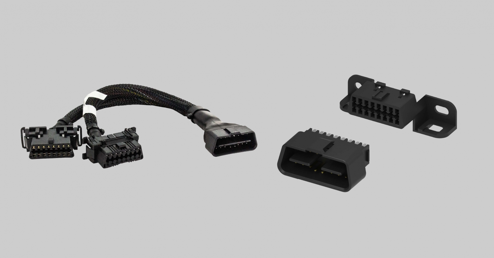
OBD2 Connectors & Cable Assemblies
OBD2 connectors and cable assemblies provide a standardized vehicle diagnostic interface for accessing diagnostic data, fault codes, and selected vehicle network information. Solutions may include diagnostic connectors, cable assemblies, and application-specific configurations based on the required vehicle interface and installation requirements. The OBD2 interface is commonly associated with a 16-pin format defined by automotive diagnostic standards.
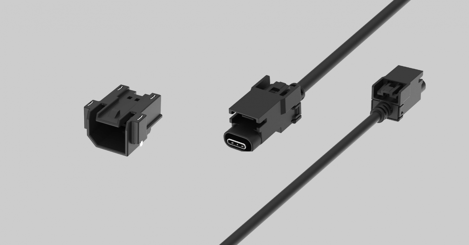
Automotive USB Type-C Connectors & Cable Assemblies
Automotive USB Type-C connectors and cable assemblies support data transfer and power delivery for in-vehicle infotainment, rear-seat entertainment, charging, service interfaces, diagnostic equipment, and selected autonomous or industrial vehicle platforms. Available solutions may include board-mount or panel-mount connector interfaces, cable assemblies, and application-specific configurations. Data rate, power delivery capability, cable length, shielding, retention features, and environmental performance depend on the selected product series and system requirements.
Environmental Design Considerations
Automotive and industrial deployments can expose connectors and cable assemblies to temperature cycling, vibration, moisture, dust, UV exposure, and chemical contamination. These conditions can affect electrical performance, mechanical retention, sealing integrity, and long-term system reliability.
Waterproof and Sealed Interfaces
Exterior-mounted cameras, sensors, antennas, and enclosure feedthroughs may require sealed interfaces to reduce moisture and contaminant ingress. Required sealing performance should be defined according to the installation location, exposure conditions, mating configuration, and actual product specification.
Related Technical Insight: Choosing an IP Protection Rating
Protection requirements for exterior cameras, vehicle-mounted sensors, antennas, and sealed enclosures should not be reduced to a general “waterproof” label. For a comparison of IP67, IP68, and IP69K under dust, immersion, and high-pressure washdown conditions, read IP Rating Guide: IP67, IP68, and IP69K Explained.
Temperature Qualification
Temperature requirements vary by vehicle location, industrial environment, installation conditions, and thermal exposure near electronics or power components. Connector and cable assembly materials should be selected according to the actual operating temperature range and duty cycle.
Vibration Resistance
Connector mating interfaces in high-vibration environments must maintain consistent electrical contact under mechanical stress. Secondary locking mechanisms, positive latching, and strain relief design can contribute to contact stability, depending on the connector and cable assembly design.
Related Technical Insight: Outdoor Camera Connectivity Challenges
For exterior cameras, agricultural machinery, construction vehicles, and outdoor sensing systems, interconnects must support high-speed video transmission while also addressing vibration, dust, moisture, temperature variation, and long-term environmental exposure. Explore outdoor camera system connectivity challenges and design considerations.
Industrial, Robotics, and Edge AI Connectivity
Industrial automation, collaborative robotics, and edge AI deployments share several connectivity challenges with automotive systems, including high-speed data transmission, reliable power delivery, mechanical retention, environmental protection, and compact integration.
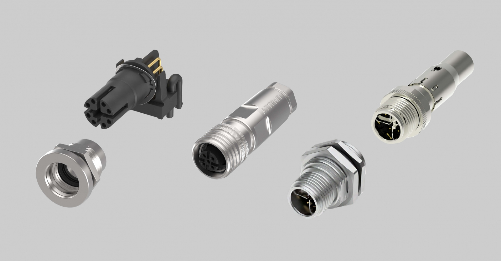
M12 Connectors & Cable Assemblies
M12 connectors and cable assemblies are commonly used in industrial automation, robotics, machine vision, and distributed I/O systems for power, signal, sensor, actuator, and industrial Ethernet connections. Available solutions may include cable-end connectors, panel-mount receptacles, overmolded cable assemblies, and customized cable configurations for equipment integration. Coding, pin count, Ethernet capability, coupling style, cable length, shielding, conductor specification, and sealing performance should be selected according to the required signal architecture, installation environment, cable routing path, and serviceability requirements.
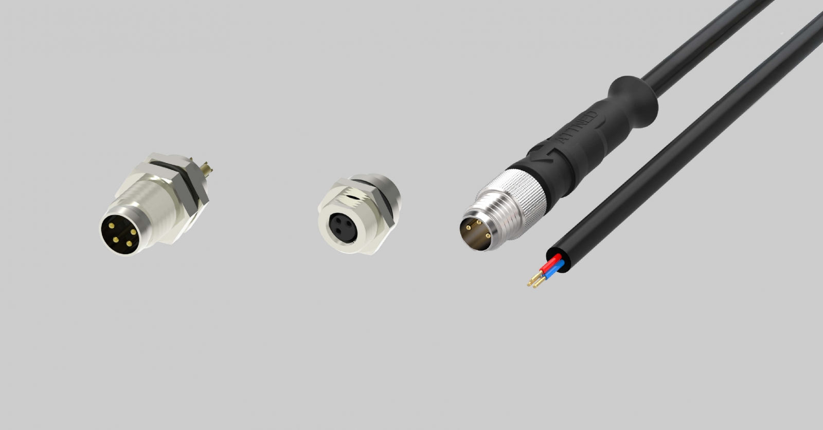
M8 Connectors & Cable Assemblies
M8 connectors and cable assemblies are commonly used for compact sensors, proximity switches, actuators, and distributed I/O interfaces where installation space is limited. Available solutions may include cable-end connectors, panel-mount receptacles, molded cable assemblies, and customized cable lengths or termination configurations. Coding, pin count, coupling style, shielding, cable routing, and sealing performance should be verified against the selected product series and the actual operating environment.
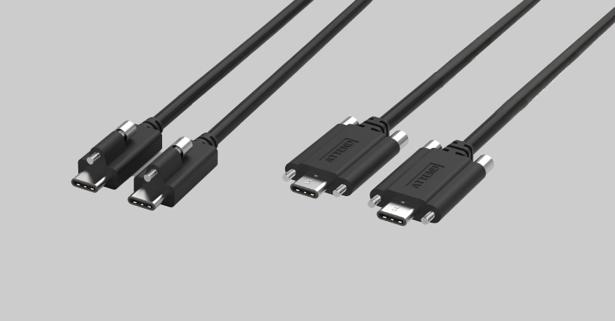
USB-C Screw-Locking Cable Assemblies
Screw-locking USB-C cable assemblies are designed for applications where cable retention is important, particularly in equipment exposed to motion, vibration, or repeated handling. The locking interface helps reduce the risk of unintended disconnection in industrial, machine vision, diagnostic, and mobile equipment applications. USB generation, data rate, power delivery capability, cable length, shielding, locking configuration, and environmental performance vary by product series and application requirements.
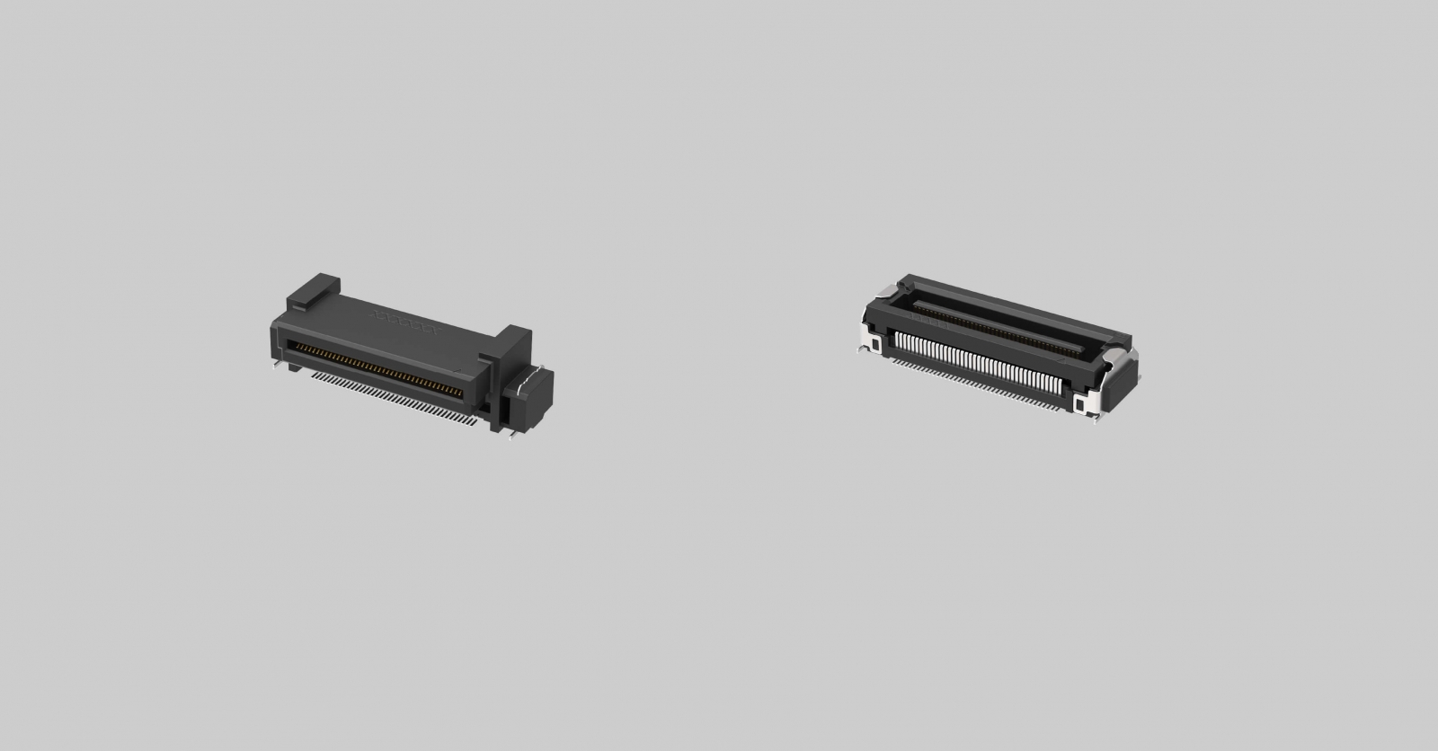
Floating Board-to-Board Connectors
Floating board-to-board connectors help accommodate board-stacking tolerance by allowing controlled X- and Y-axis movement during mating. Pitch, stack height, signal performance, and mechanical tolerance depend on the selected product series.
Edge AI Camera Systems
Edge AI camera systems integrate camera modules, inference processors, storage, power management, and communication interfaces in compact enclosures deployed near the point of perception. These systems often require reliable high-speed video links, environmental protection, efficient thermal design, and compact board-level integration.
Related Technical Insight: Edge AI Connectivity in Harsh Environments
Edge AI systems are often deployed close to the point of perception, where high-speed imaging and compute integration must be considered alongside vibration, dust, moisture, temperature variation, and cable retention. Read the guide to Edge AI connectivity in harsh environments.
High-Speed Signal Integrity Design
High-speed signal transmission places system-level requirements on the complete interconnect channel. Engineers should evaluate connector, cable assembly, and PCB transition options against actual operating conditions rather than headline specifications alone.
Impedance Control
High-speed signal channels are designed around a target characteristic impedance. Engineers should evaluate impedance continuity across the connector, cable assembly, terminations, PCB transitions, and any intermediate interfaces used in the selected signal path.
Insertion Loss, Return Loss, Shielding, and EMI
Insertion loss, return loss, shielding effectiveness, termination quality, grounding strategy, and cable routing all affect high-speed transmission quality. These factors should be evaluated across the complete channel under relevant operating conditions.
Full-Channel Validation
The most reliable way to evaluate interconnect performance is to validate the complete channel from the source interface to the destination under conditions that reflect the actual operating environment, including cable routing, connector mating, PCB layout, temperature, and vibration.
Engineering Selection Framework
Interconnect selection should begin with system requirements rather than a connector catalog alone. The framework below summarizes a practical evaluation sequence for narrowing connector options in a new system design.
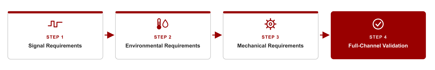
Engineering selection framework for evaluating signal, environmental, mechanical, and full-channel validation requirements.
Step 1: Signal Requirements
- What signal type is being transmitted?
- What is the operating frequency or data rate?
- What impedance must be maintained?
- Is power delivery required over the same cable or signal path?
- Is bidirectional communication or reverse-channel signaling needed?
Step 2: Environmental Requirements
- What are the operating temperature limits?
- Is the connector exposed to vibration, shock, or repeated mating cycles?
- Is environmental sealing required? If so, what protection level is needed for the actual installation environment?
Step 3: Mechanical and Cable Assembly Requirements
- What space is available for the connector and cable assembly?
- What cable type, routing path, routing length, minimum bend radius, shielding, and strain-relief requirements apply?
- Is an overmolded, panel-sealed, or customized cable assembly required?
- Is panel-mount integration needed?
- What interface is required at the camera module, sensor, cable assembly, panel entry point, and processing unit?
- Are multiple identical channels required?
- What is the serviceability requirement?
Step 4: System-Level Validation
Once the connector type is identified, the cable assembly, PCB transitions, board-side interfaces, shielding strategy, cable routing, and installation conditions should be evaluated together as a complete signal path. A connector specification alone does not confirm system-level performance.
Key Takeaways
- Connector selection should begin with signal, mechanical, environmental, and system-validation requirements.
- Camera, ADAS, robotics, and edge AI systems may require different connector families depending on signal architecture, environmental exposure, mechanical integration, and deployment conditions.
- Specification-sensitive connector decisions should be verified against current product documentation, qualification data, and system-level requirements.
Frequently Asked Questions
Automotive camera systems commonly use FAKRA and Mini FAKRA for coaxial camera links, particularly in GMSL2 or FPD-Link III architectures. HSD, HS-MTP, and other shielded differential interfaces may be used where the system relies on LVDS, Automotive Ethernet, or other differential signaling approaches. Final connector selection depends on the camera module interface, required data rate, cable routing, environmental exposure, and whether the architecture uses Power over Coax.
Engineers typically begin with the signal, power, and communication requirements of the sensor, actuator, camera, or controller. They then evaluate installation space, coupling type, vibration exposure, sealing needs, cable routing, and serviceability. M12 and M8 circular connectors are common choices in industrial robotics because selected product series offer coding options, secure coupling, and environmental protection for field-connected equipment.
Signal integrity determines whether a high-speed channel transmits data reliably across its full operating range. Poor impedance continuity, insufficient shielding, or marginal termination quality can degrade signal quality even when the connector meets its standalone frequency specification. Evaluating signal integrity at the system level — across the connector, cable assembly, and PCB transition — helps prevent intermittent failures that are difficult to diagnose after deployment.
Both use 50-ohm coaxial interfaces with mechanical keying and color-coding for automotive RF applications. Mini FAKRA is designed for higher-density packaging and can offer a substantially smaller footprint than standard FAKRA, depending on the selected configuration. Frequency capability, mechanical dimensions, and system suitability should be verified against the relevant product documentation.
Coaxial camera connectors provide the RF interface between camera modules and vehicle processing platforms. They maintain 50-ohm impedance continuity, shielding effectiveness, and mechanical retention across the coaxial cable run from camera to ECU. FAKRA and Mini FAKRA are widely used coaxial interfaces in automotive camera and RF connectivity architectures. Waterproof panel-mount variants are used for exterior-mounted camera modules that require environmental sealing at the body panel interface.
OBD2 (On-Board Diagnostics II) commonly uses the SAE J1962 diagnostic connector, typically in a 16-pin configuration, to provide access for diagnostic tools, telematics devices, and vehicle data applications.
In automotive applications, USB-C connectors may support charging and data transfer. Where the host, device, cable, and port architecture support the required Alternate Mode or USB4 capability, they may also support display connectivity. In industrial and robotics applications, screw-locking USB-C variants are used to provide secure connector retention in equipment subject to movement or vibration, supporting diagnostic, charging, or data transfer use cases within automation environments.
M8 and M12 refer to the nominal thread diameter of the connector coupling mechanism: 8 mm and 12 mm, respectively. M12 connectors are widely used in industrial automation and are available in configurations that support higher pin counts, power, signal, and industrial Ethernet applications. M8 connectors are commonly used for compact sensors and actuator connections where installation space is more limited. Available coding, coupling method, and sealing performance depend on the selected product series.
Sealed panel-mount connectors are used when an external cable from an outdoor camera, antenna, sensor, or other field device must pass through a vehicle body panel or equipment enclosure. They help provide environmental protection at the panel entry point while supporting the required electrical or RF interface. Actual sealing and signal performance depend on the mated connector system, panel design, cable assembly, and installation conditions.
Yes. The connector is a transition point in the signal channel, and its impedance continuity, shielding design, and termination quality all affect transmission performance. Even when a connector meets the required frequency range, system performance can still be affected if return loss, shielding continuity, or termination quality is insufficient. Signal integrity should be evaluated across the complete channel, not at the connector level alone.
The choice depends on the camera module, host processor, and transmission architecture. GMSL2 and FPD-Link III systems commonly use coaxial cable links, where FAKRA or Mini FAKRA may be selected as the external interface. Automotive Ethernet systems use differential-pair transmission, where HSD, HS-MTP, or other compatible shielded interfaces may be used depending on the required architecture. The final interface should be defined by the system specification, channel design, and environmental requirements.
Related Connector Solutions
Rugged coaxial interconnects designed to support reliable signal transmission across ADAS cameras, surround-view systems, telematics, and in-vehicle vision platforms.
Explore the Solution >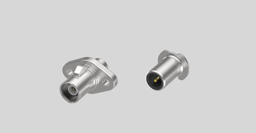
Explore the design considerations behind high-speed twisted-pair interconnects for camera, display, infotainment, and automotive Ethernet applications.
Explore the Solution >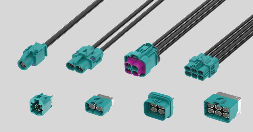
High-speed twisted-pair connectivity for reliable data transmission across automotive cameras, infotainment, telematics, and in-vehicle networking systems.
Explore the Solution >Related Technical Insights
GMSL2 vs Ethernet Camera Interfaces
Compare GMSL2 and Automotive Ethernet camera architectures across bandwidth, latency, power delivery, cable routing, scalability, and system integration requirements.
Read the Article >.png)
See how connector and interconnect choices affect bandwidth, signal integrity, synchronization, and system scalability across multi-camera Vision AI platforms.
Read the Article >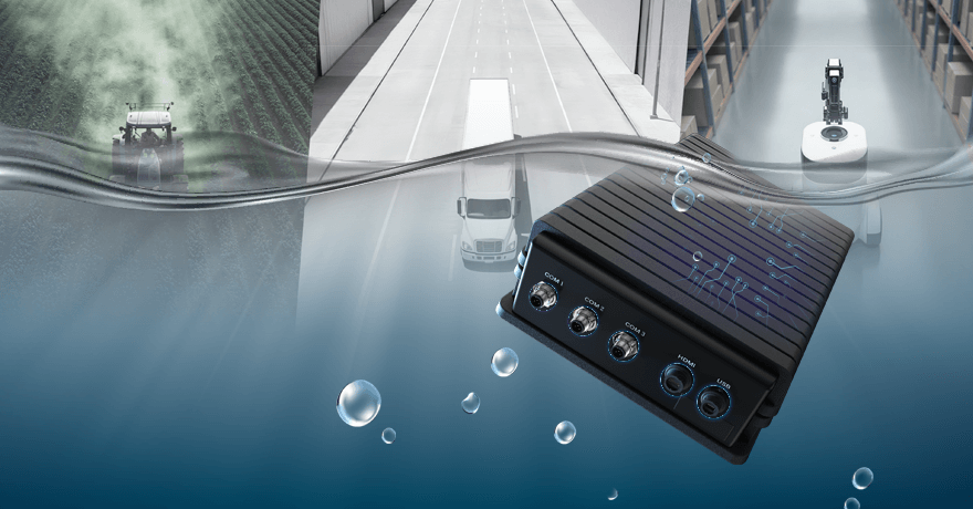
Understand how IP67, IP68, and IP69K protection ratings differ—and how to choose the right level of water, dust, and high-pressure washdown protection for your application.
Read the Article >