
Interface selection is not just a specification comparison —
it defines system behavior, from architecture and synchronization to physical layer design
In Vision AI system design, discussions often focus on model accuracy, resolution, and compute performance. However, field failures rarely originate from these layers. Instead, they emerge from how image data is transmitted, synchronized, and maintained across the system.
As multi-camera architectures become standard in robotics, automotive, and industrial inspection systems, the choice between GMSL2 and Ethernet is no longer a simple interface decision. It directly affects system stability, synchronization accuracy, and long-term deployment reliability.
This article examines the structural differences between these two approaches, the technical constraints engineers often overlook, and how interface selection influences system behavior in real-world environments.
System Architecture Differences: SerDes Link vs Network-Based Transmission
At a system level, GMSL2 and Ethernet represent two fundamentally different data transmission models.
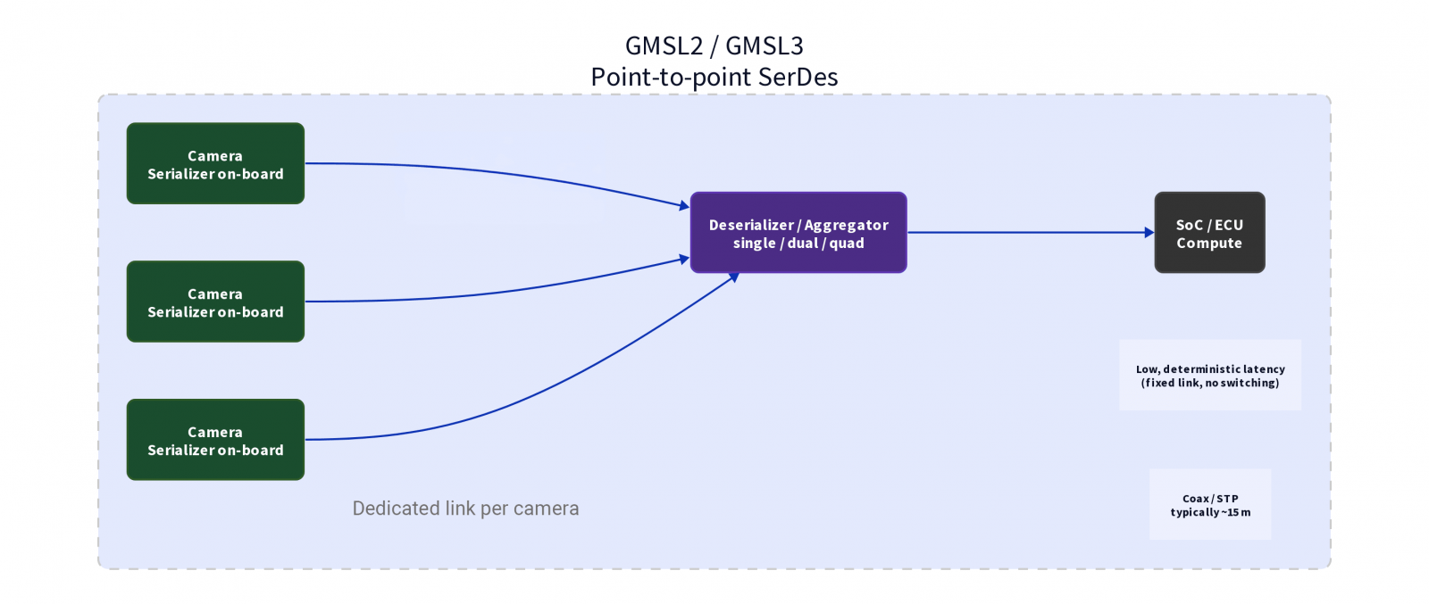
GMSL2 is built on a SerDes (Serializer/Deserializer) architecture. Image data is serialized at the camera module and transmitted through a dedicated point-to-point link. GMSL2 supports transmission rates of up to approximately 6 Gbps, while GMSL3 reaches approximately 12 Gbps, typically over coaxial or shielded twisted pair cable. Effective transmission distance reaches up to approximately 15 meters, though actual range varies depending on SerDes generation, cable quality, and system design. The transmission path is fixed, without packet switching or network-layer processing, enabling highly predictable transmission behavior.
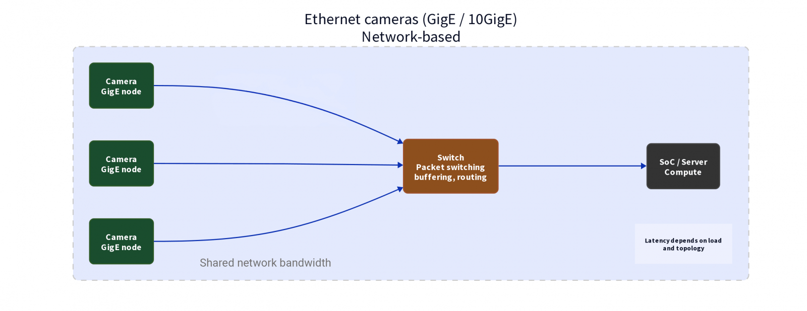
Ethernet treats image data as network traffic. Cameras act as nodes, transmitting packets through switches before reaching compute. Standard GigE supports 1 Gbps; 10GigE reaches 10 Gbps. Without repeaters, a single cable segment typically spans up to approximately 100 meters, extendable further through network equipment. The data path is dynamic and shared across devices.
This fundamental difference defines how systems scale and how data behaves under load.
Latency and Determinism: Fixed Data Path vs Network Variability
The difference in latency behavior between GMSL2 and Ethernet stems primarily from their transmission architectures.
GMSL2 provides a relatively deterministic data path. Each camera has a dedicated link, and latency typically remains in the microsecond (µs) range with low variation. This characteristic makes it well-suited for systems requiring stable timing and real-time response — such as ADAS surround view camera arrays, autonomous vehicle sensor fusion, or industrial AMR real-time visual control loops.
Ethernet introduces variability due to packetized transmission, switch buffering, and network load. In practice, latency typically falls in the sub-millisecond to millisecond range, depending on network architecture and the degree of optimization applied. Mechanisms such as QoS and Time-Sensitive Networking (TSN) can reduce this variability, but require additional system-level configuration.
In practice, systems that appear stable in lab conditions may exhibit unpredictable timing behavior once deployed.
Synchronization Challenges: Hardware Timing vs Protocol Alignment
Time synchronization is one of the most underestimated factors in multi-camera systems.
In GMSL2 architectures, synchronization is typically implemented at the hardware level — for example, through GPIO tunneling to distribute timing signals, allowing multiple sensors to share a common time reference. Under appropriate system design, microsecond-level synchronization accuracy is achievable, though actual performance depends on system configuration and hardware implementation.
Ethernet synchronization approaches vary by system design. Network-only architectures rely on PTP (IEEE 1588 Precision Time Protocol), whose accuracy is highly dependent on network equipment, topology, and hardware support across all nodes. In industrial applications, it is also common to use a dedicated M8 GPIO connector to provide hardware trigger signals, enabling multi-camera synchronization without relying on network protocols. This approach offers greater determinism than pure software-based synchronization.
When synchronization is misaligned, the issue rarely presents as an outright system failure. Instead, it manifests as subtle anomalies — misaligned frames, unstable object tracking, or inconsistent depth estimation.
Bandwidth vs Data Flow Stability
Bandwidth is an important metric, but insufficient on its own to evaluate system performance.
In GMSL2 systems, each link is dedicated to a single camera — 6 Gbps per link for GMSL2, 12 Gbps for GMSL3 — with no contention between devices. In common designs, a single deserializer can aggregate up to four camera streams. Overall system performance still depends on the processing capacity of the backend SoC.
In Ethernet systems, bandwidth is shared. Even with 10 GigE total capacity, data streams must compete for transmission through the network. Under certain load conditions, intermittent latency spikes and brief congestion events can occur.
As a result, bandwidth availability does not guarantee stable data delivery.
Physical Layer Considerations: The Role of Interconnect Design
In high-speed imaging systems, physical interconnect design directly affects signal quality and long-term stability.
In GMSL2 architectures, the signal path typically spans three stages: the board-level RF interface at the camera module, the transition layer into the transmission medium, and the coaxial or shielded twisted pair cable link connecting to the compute unit.
Each of these transition points involves impedance continuity, contact stability, and mechanical structural integrity. At transmission rates in the multi-Gbps range, even minor discontinuities or contact variation can compromise signal integrity over time.
Ethernet systems use standardized cabling and connectors, but performance remains dependent on cable quality, shielding design, and network topology.
Connector Selection: FAKRA, Mini-FAKRA, and Industrial Ethernet Circular Connectors
In the physical layer of Vision AI systems, RF connector and industrial circular connector selection is a critical factor in signal integrity and system reliability.
.png)
GMSL2/GMSL3 Systems: FAKRA and Mini-FAKRA
Mini-FAKRA is the compact evolution of FAKRA, offering a smaller form factor while delivering higher connector density. A single Mini-FAKRA housing can integrate up to four coaxial channels (Quad Mini-FAKRA). It is particularly suitable for space-constrained multi-camera layouts such as ADAS surround view systems or Driver Monitoring Systems (DMS).
GigE Vision Industrial Camera Systems: M12 and M8
In industrial Ethernet camera systems, the dominant configuration uses a dual-connector architecture: an M12 connector handles GigE data transmission and power delivery using PoE, while an M8 connector handles GPIO signals including hardware trigger input and strobe output.
.png)
GMSL2 vs Ethernet System Comparison
| Dimension | GMSL2 / GMSL3 | Ethernet Cameras |
|---|---|---|
| Architecture | Point-to-point, deterministic | Network-based, distributed |
| Transmission Rate | ~6 Gbps (GMSL2) / ~12 Gbps (GMSL3) | 1 Gbps (GigE) / 10 Gbps (10GigE) |
| Latency | Microsecond range, low variation | Sub-millisecond to millisecond, network-dependent |
| Synchronization | Hardware GPIO tunneling, µs-level precision | PTP protocol or M8 GPIO hardware trigger |
| Bandwidth Model | Dedicated per link, no contention | Shared across devices |
| Cable & Distance | Coax or STP, up to ~15 meters | Twisted pair, ~100 meters or more |
| Power Delivery | PoC (Power over Coax) | PoE (Power over Ethernet) |
| Physical Connectors | FAKRA / Mini-FAKRA | M12 (data/PoE) + M8 (GPIO) |
| Deployment Focus | Automotive, embedded, real-time systems | Distributed, long-range, industrial networks |
Note: In mass production, GMSL systems may reduce overall BOM and assembly complexity through single-cable integration (PoC), while Ethernet benefits from scalability within existing network infrastructure.
Common Misconceptions Engineers Often Overlook
- Misconception 1: Higher bandwidth guarantees better performance. Latency variation and synchronization errors can degrade performance even when bandwidth is sufficient.
- Misconception 2: Ethernet inherently scales better. In multi-camera real-time systems requiring microsecond-level synchronization, scaling can amplify instability.
- Misconception 3: Synchronization can be solved entirely in software. Hardware support remains critical for real-world accuracy.
- Misconception 4: Interface selection can be changed later. Changing interface late in the design cycle typically requires re-validating the entire signal path.
Selection Considerations: Matching Interface to System Requirements
Scenarios suited for GMSL2/GMSL3:
- ADAS surround view or forward-facing cameras requiring low latency and high synchronization precision
- Industrial AMR real-time visual control loops
- Space-constrained embedded platforms where PoC enables single-cable integration
- High-EMI environments (engine compartments, welding facilities, etc.)
Scenarios suited for Ethernet industrial cameras:
- Large-scale industrial vision deployments where camera-to-compute distances exceed 15 meters
- Systems requiring integration with existing network infrastructure
- High-speed production line inspection using PTP or M8 GPIO triggers
FAQ
Q1: Is Ethernet always the better choice for scalable systems?
Q2: Why do systems fail even when bandwidth appears sufficient?
Q3: Is GMSL2 suitable for multi-camera applications?
Q4: How do I choose between FAKRA, Mini-FAKRA, M12, and M8 connectors?
Q5: Can synchronization be solved entirely in software?
Q6: What is the most common cause of system instability in real deployments?
Conclusion: Interface Selection as an Architectural Decision
In modern Vision AI systems, the limiting factor is no longer model capability — it is the stability of the data pipeline.
GMSL2 and Ethernet represent two different system design philosophies. One prioritizes predictability and control; the other emphasizes flexibility and scalability.
Whether a system succeeds in real-world deployment often depends on how these trade-offs are evaluated early in the design process.
Core Recommendations
- Choose GMSL2/GMSL3 when you need deterministic low latency, precise hardware synchronization, and operation in high-EMI or space-constrained environments.
- Choose Ethernet when camera-to-compute distance exceeds 15 meters, or when integrating into existing large-scale network infrastructure.
- Always define latency tolerance, synchronization precision, transmission distance, and environmental requirements before selecting the interface.
- Pay special attention to physical layer design — connector selection and impedance matching directly impact long-term field reliability.