
Cable quality determines signal integrity
LVDS System Design Practical Trilogy | Part 2: The Cable FactorIn the previous article, we clarified LVDS's technical nature. However, even with understanding of differential signal principles, actual systems can still have problems in unexpected places—and cables are precisely the most commonly underestimated link.
Preface: Cables Are Part of the Signal Path
In LVDS systems, overall performance depends on the complete signal path, not individual component specification compliance. Besides the differential driver and receiver, the transmission medium includes PCB traces, cables, and connectors. Any discontinuity in electrical characteristics at any link can cause signal integrity degradation.
Worth noting: cables are often treated as "accessories" rather than "design requirements" in early design stages, so they receive relatively less attention during design review and verification phases. This gap often only becomes apparent during longer cable lengths, harsher environments, or mass production—and by this time, the correction cost is already alarmingly high.
Why Cables Are Often Overlooked
Common reasons cables are underestimated:
- Design and review resources are mostly concentrated on IC selection and PCB controlled impedance design. This makes sense—PCB layout complexity is indeed higher, and once boards are sent out, they're difficult to modify.
- Short-distance test conditions (like 30cm cables on lab benches) make it difficult to amplify cable defects. Under these conditions, even if cable quality is poor, signal degradation may still be within acceptable ranges.
- Electrical differences and process variations in cables aren't easily identified visually. Two identical-looking cables may have completely different internal structures—and these differences only become apparent during measurement or actual operation.
Four Essential Electrical Characteristics Cables Must Meet
LVDS relies on differential transmission to improve noise immunity and reduce EMI. To maintain predictable transmission quality in the "cable segment," cables must meet at least these four electrical characteristics:
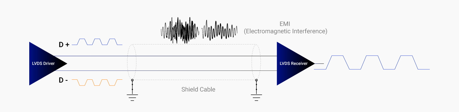
Illustration of an LVDS differential pair transmitted through a shielded cable.
1. Differential Pair Symmetry
The two conductors of a differential pair need consistency in both electrical and geometric terms, including length, capacitance, resistance, and structural symmetry. Mismatches introduce skew, reducing noise margin and increasing jitter risk.
In practice, skew's impact may manifest as: horizontal stripes in images, sporadic data errors, or anomalies at specific resolutions. The common characteristic: "instability"—sometimes normal, sometimes not, often related to temperature and cable bending state.
2. Consistent Differential Impedance
LVDS systems typically target 100Ω differential impedance. Cables need to maintain impedance consistency across their entire length, not just meet the target locally. Impedance discontinuities cause reflections, and superimposed reflections degrade signal edges and eye diagram quality, further affecting system bit error rate.
There's a common misconception: "The cable spec says 100Ω, so there's no problem." In reality, impedance needs consistency across the entire cable and all frequency ranges. Cheap cables might meet specs in some frequency bands but deviate at critical frequencies—precisely at LVDS signal's main frequency components.
3. Shielding Effectiveness
Differential transmission has common-mode noise rejection capability, but in automotive and industrial environments, it still relies on effective shielding to reduce external EMI coupling. Insufficient shielding may cause common-mode energy to increase, consuming the receiver's anti-interference capability, ultimately forming unstable and difficult-to-reproduce field problems.
A system tested completely normally in the lab but started having sporadic noise after vehicle installation. Finally discovered the cable's shielding layer had broken at a bending point, which happened to be near thethe drive motor — the area with strongest electromagnetic interference. After switching to a cable with more complete shielding, the problem was resolved.
4. Twist Pitch Consistency
Differential pair twist pitch affects coupling degree, differential impedance, and crosstalk. If twist pitch is inconsistent along cable length, it causes uneven spatial distribution of electrical characteristics, leading to unpredictable signal quality; in cables with multiple parallel pairs, it may also increase inter-channel crosstalk risk.
This characteristic is particularly critical in multi-channel LVDS systems. For example, a display panel might use 4 or 8 LVDS channel pairs transmitting simultaneously. If one pair has inconsistent twist pitch, it might cause crosstalk to other channels, leading to color anomalies or noise in specific image areas.
Distance Effects: Cable Length Amplifies All Discontinuities
Cable defects' impact is cumulative. Under short cable conditions, slight impedance mismatches or insufficient shielding might still fall within acceptable ranges; when cable length increases, reflection paths lengthen, noise coupling increases, and skew's relative impact becomes significant—system stability can decline rapidly.
If actual applications will use 2-meter cables, test with 2 meters, not validate with 30cm short cables. Further, if the system needs to operate at different temperatures and different bending states, these conditions should also be included in test scope.
The True Cost of Cheap Cables
Common risks with low-cost cables include:
- Mechanical stress causing characteristic drift: Bending, vibration, thermal cycling change pair geometric structure, affecting electrical characteristics. Cheap cable structural strength is often insufficient to withstand these stresses, leading to performance degradation after long-term use.
- Inconsistent termination quality: Termination process consistency directly affects contact impedance and impedance continuity. Cheap cable termination might use simplified processes, leading to batch-to-batch or within-batch quality variation.
- Process variation amplifying mass production risk: When cable process control isn't rigorous, every batch, every cable's electrical parameters might differ. This isn't easily discovered during small-scale validation but causes yield issues during mass production.
- Increased debugging costs: Intermittent faults are the most difficult problem type. When the problem isn't "completely unusable" but "sometimes acts weird," engineering teams might need many times normal debugging time and resources.
Practical Recommendations: How to Choose Suitable LVDS Cables
- Require suppliers to provide complete electrical parameter data, including differential impedance, skew, shielding effectiveness, etc., and confirm these parameters are measured at actual cable lengths, not just theoretical values.
- Prioritize cable specifications validated in similar applications. If suppliers can provide actual cases or application references, it means the cable has been market-validated, with relatively lower risk.
- Use actual cable lengths and environmental conditions for testing during validation phase. Don't compromise test conditions for lab convenience—these compromises might become serious problems after mass production.
- Establish incoming inspection mechanisms for cables. Even for the same cable model, different batches might have quality differences. Sampling key parameters can identify problems early.
- Maintain appropriate signal margin in system design. Don't let the system operate right at the spec edge—this makes any small variation potentially cause failure.
Conclusion: Cables Cannot Exist Independently
Even if cable electrical characteristics are well-designed, they still need to be "properly continued" at the endpoints. The transition zone between cable and connector is where impedance discontinuity and shielding interruption most commonly occur, and is also the most easily overlooked risk point in LVDS systems.
A cable with perfect specifications, if differential pair symmetry or shielding continuity is broken during termination, will still cause system problems. Therefore, LVDS reliability assessment must extend from "cable" to systematic "cable-connector" termination design.