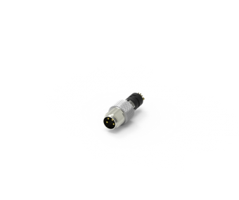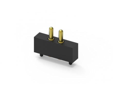

Pogo Pin, XX Pin, 2.54P, 10u'', 7.5H 3.1 Stroke, Cap, SMT
303B-443118-254-XX
Pogo Pin, XX Pin, 2.54P, 10u'', 7.5H 3.1 Stroke, Cap, SMT
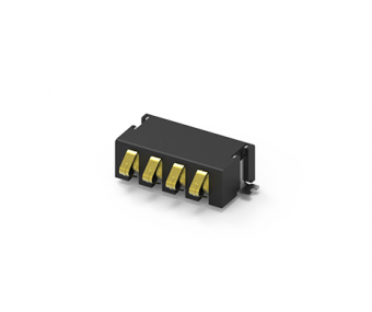
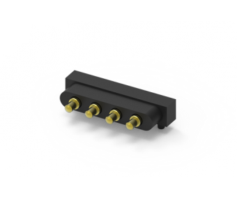
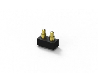
ATTEND’s Pogo Pin connectors combine gold-plated surfaces with superior structural design, ensuring stable current transmission and long-term reliability. Whether for consumer electronics, industrial equipment, or testing interfaces, our Pogo Pins deliver innovative, high-performance connection solutions that give your designs a competitive edge.
ATTEND’s Pogo Pin connectors combine gold-plated surfaces with superior structural design, ensuring stable current transmission and long-term reliability. Whether for consumer electronics, industrial equipment, or testing interfaces, our Pogo Pins deliver innovative, high-performance connection solutions that give your designs a competitive edge.
Share:
MAIN FEATURES
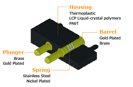
ATTEND’s Pogo Pin connectors are engineered for superior performance and reliability, making them ideal for various applications such as consumer electronics, industrial equipment, medical devices, and testing interfaces.
- High Stroke: Offers excellent flexibility, ensuring reliable connections even under dynamic conditions.
- High Durability: Built to endure thousands of usage cycles, maintaining optimal performance over time.
- Long Lifetime: Crafted with premium materials to guarantee extended operational longevity.
- Ease of Attaching: Simplified design for quick and secure installation.
- Stable Current Flow: Ensures consistent and efficient power and signal transmission.
Applications:
- Antenna Systems
- Board-to-Board Connections
- Medical Devices
- Tracking Devices
- Portable Electronics
| Product Comparison Overview | ||||
| Variation | Pin Count | Working Height | Current Rating | Voltage Rating |
| Single | 1 Pin | 2.6-6.8mm | 1-2A | 12-30V |
| Multiple | 2-4 Pin | 3.9-7.0mm | 1-2A | 12-30V |
| Magnetic&Waterproof | 2-5 Pin | 4.0-5.5mm | 2A | 5-12V |
| Magnetic | 2-4 Pin | 4.0-6.0mm | 1-3A | 5-12V |
SPECIFICATION
| Current Rating | 2A |
|---|---|
| Voltage Rating | 30V |
| Contact Resistance | 50mΩ Max. at working height |
| Durability | 10,000 Cycle |
|---|---|
| Spring Force | 45g±15g at working height |
- To avoid arcing issue, the adaptor start to power supply after connector mated fully.
- Based on Engineer drawing, shall not exceed one the working height the maximum allowed compress.
- To ensure the best usage, please operate it based supply after connector mated fully.
DOWNLOAD
| CATEGORY | TITLE | SIZE | FILE TYPE | DOWNLOAD |
|---|---|---|---|---|
| Drawing | 303B-443118-254-XX | 52 KB | PDF: Drawing | |
| 3D | 303B-443118-254-XX | 33 KB | RAR: 3D File |